Schematic Diagram of Claw Couplings
Rokee is a well-known high-quality Claw Coupling manufacturer from China, Learn more about schematic diagram of claw couplings, pls contact Rokee technical engineer, we can customize claw coupling according to user drawings, alternatively, if the user provides claw coupling parameters, we can select the model and design drawings for you, Rokee also support wholesale and export.

The claw coupling is composed of two semi-couplings with convex claws and a plum-shaped flexible non-metallic element whose hardness can be adjusted. By embedding the plum-shaped flexible element into the two semi-couplings to realize the connection, claw coupling has the characteristics of compensating the relative displacement of the two axes, reducing vibration and buffering, simple structure and easy maintenance without lubrication. The claw coupling is a widely used coupling, also called a claw coupling, which is composed of two metal claw discs and an elastic body. The two metal claws are generally made of No. 45 steel, but aluminum alloys are also useful when load sensitivity is required.
![Schematic Diagram of Claw Couplings,LMPK/MLPK Plum Blossom Coupling]()
LMPK/MLPK Plum Blossom Coupling
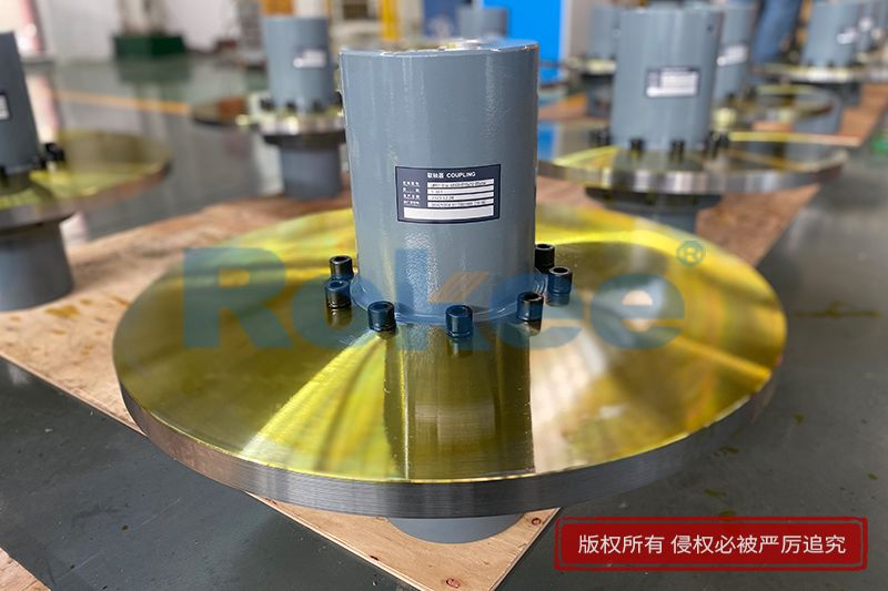
LMPK/MLPK Plum Blossom Coupling adopts split brake disc design, suitable for situations where braking is required and eliminating the need of axially moving the semi-coupling when replacing the elastomer.View More![Schematic Diagram of Claw Couplings,LMZ-II/MLL-II Plum Blossom Coupling]()
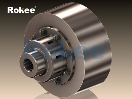
LMZ-II/MLL-II Plum Blossom Coupling
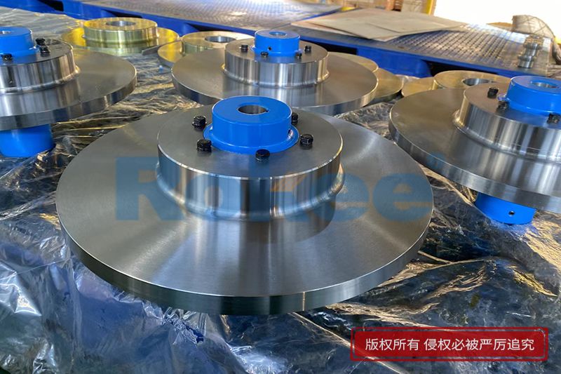
LMZ-II/MLL-II Plum Blossom Coupling adopts integral brake wheel design, suitable for situations where braking is required.View More![Schematic Diagram of Claw Couplings,LMZ-I/MLL-I Plum Blossom Coupling]()
LMZ-I/MLL-I Plum Blossom Coupling
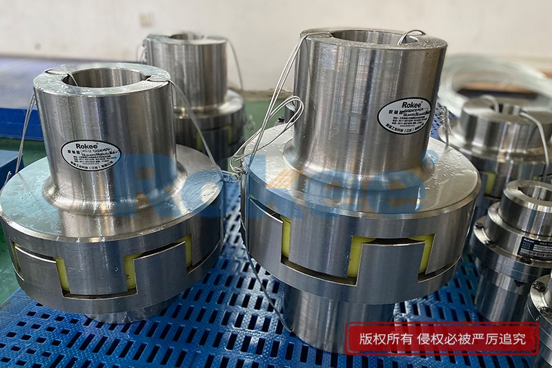
LMZ-I/MLL-I Plum Blossom Coupling adopts split brake wheel design, suitable for situations where braking is required.View More![Schematic Diagram of Claw Couplings,LMS/MLS Plum Blossom Coupling]()
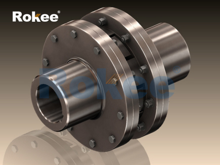
LMS/MLS Plum Blossom Coupling
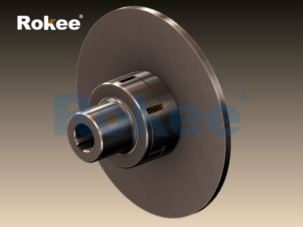
LMS/MLS Plum Blossom Coupling adopts double transition flange connection, which eliminates the need of axially moving the semi-coupling when replacing the elastomer.View More![Schematic Diagram of Claw Couplings,LMD/MLZ Plum Blossom Coupling]()
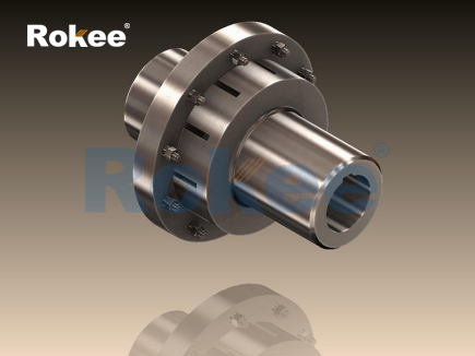
LMD/MLZ Plum Blossom Coupling
LMD/MLZ Plum Blossom Coupling is added with transition connection, which eliminates the need of axially moving the semi-coupling when replacing the elastomer.View More![Schematic Diagram of Claw Couplings,LM/ML Plum Blossom Coupling]()
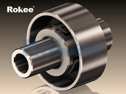
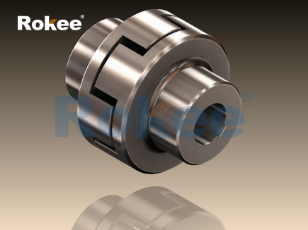
LM/ML Plum Blossom Coupling
LM/ML Plum Blossom Coupling is the basic form of this series of couplings.View More
« Schematic Diagram of Claw Couplings » Post Date: 2024/4/27 , https://www.rokeecoupling.net/blog/schematic-diagram-of-claw-couplings.html