Flexible Shaft Couplings
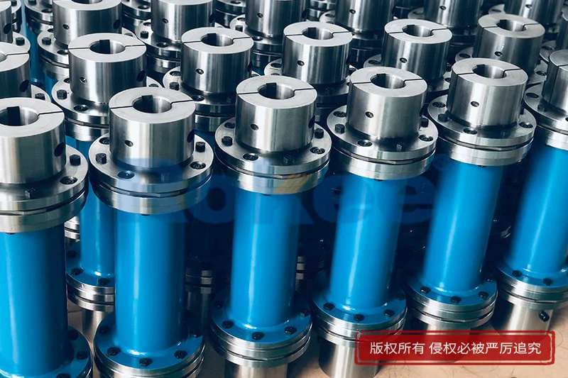
Flexible Shaft Couplings transmit torque & compensate angular, radial & axial misalignment. Dampen vibration, absorb shock for pumps, motors & industrial machinery. Standard & custom sizes available. Rokee is a flexible shaft couplings supplier in China. We support custom orders and offer direct factory sales, providing reliable products with flexible solutions for global clients.
Flexible shaft couplings are mechanical components for connecting rotating shafts to transmit torque and motion. Different from rigid couplings, they compensate for radial, angular and axial misalignment via elastic deformation or limited relative movement of internal parts. They can buffer shock and reduce vibration transfer. Available in multiple types with varied structures and materials, they are widely used in pumps, automation equipment and general machinery. Proper alignment during installation, rational type selection and regular inspection help guarantee stable transmission and prolong service life.
Flexible shaft couplings are mechanical connecting components used to join two rotating shafts for the transmission of torque and rotational motion. Unlike rigid couplings, they possess controlled elasticity or movable clearance inside the structure, which enables them to accommodate unavoidable misalignment between coupled shafts during operation. Such misalignment commonly includes radial offset, angular deviation and axial displacement. While reliably transferring power, these couplings also mitigate vibration, dampen shock loads and reduce the transmission of noise between driving and driven equipment. They serve as a vital intermediate part in rotating machinery systems and balance the requirement of stable power transmission and tolerance for assembly and operation deviations.
Classification and Common Types
Flexible shaft couplings can be sorted into several major categories according to their flexible implementation forms. The first group relies on elastic elements for deformation compensation, including elastomer couplings, disc couplings and diaphragm couplings. The second group achieves misalignment adaptation through relative sliding or rolling of built-in movable components, represented by gear couplings and chain couplings. The third type adopts structural bending flexibility, such as bellows couplings and spiral slit couplings.
Commonly applied models cover jaw couplings, tyre couplings, disc couplings, diaphragm couplings, bellows couplings, Oldham couplings, gear couplings and roller chain couplings. Each type follows a distinct compensation mechanism and exhibits differentiated performance boundaries, so they are selected separately to match different torque levels, rotating speeds and misalignment allowance requirements.
Structural Composition and Materials
A typical flexible shaft coupling generally consists of two hub bodies mounted respectively on the driving shaft and driven shaft, plus one or more flexible intermediate parts. Some configurations also contain fastening assemblies such as clamping rings, bolts and locking rings to secure the hubs and maintain relative positioning of all components.
Hub materials are widely chosen from carbon steel, alloy steel and aluminium alloy. For lightweight and low-inertia scenarios, aluminium alloy is preferred. Elastic intermediate components adopt diverse materials based on working demands: polyurethane, rubber and thermoplastic materials are used for elastomer parts; stainless steel or alloy steel is the primary material for metal flexible parts including diaphragms, bellows and discs. Surface treatments may be applied to metal components to improve resistance against oxidation and corrosion under humid or contaminated surroundings.
Working Principle
When the driving shaft rotates, torque is transferred through the coupling hub to the flexible intermediate unit and then delivered to the hub connected to the driven shaft, driving the whole load side to rotate synchronously. When misalignment exists between the two shafts, the flexible component deforms elastically or allows limited relative displacement between matching parts. This deformation or micro displacement absorbs the offset instead of imposing extra bending stress on the shafts, bearings and supporting structures.
Under sudden load impact, the elastic element can store and release partial energy to buffer peak torque. For high-speed operation, the coupling keeps consistent rotation speed transmission as long as the misalignment stays within the allowable range of its structural design.
Features and Advantages
The core merit of flexible shaft couplings lies in their capacity to tolerate shaft misalignment without sacrificing basic torque transmission capacity. Elastic types can effectively absorb shock and suppress vibration propagation, which helps extend the service life of bearings, seals and other precision parts on the connected equipment. Many types have compact overall dimensions and low rotational inertia, suitable for frequent start-stop and forward-reverse switching conditions.
Metal flexible couplings can maintain stable performance under a wide temperature range and show excellent resistance to fatigue. Elastomer couplings feature simple assembly, low noise and good insulating properties. Compared with rigid connection schemes, they reduce the precision requirement for shaft alignment during installation and lower the risk of premature component failure caused by assembly errors.
Applicable Conditions and Industry Sectors
These couplings fit operating environments where slight shaft misalignment is inevitable, shock load occurs intermittently or vibration isolation is required. Operating parameters cover low-speed heavy-torque transmission and high-speed precision transmission. They are not suitable for situations with excessive misalignment beyond the designed limit, strong chemical erosion that destroys elastic materials, or environments with continuous high temperature exceeding the temperature resistance threshold of the selected components.
They are widely deployed in general machinery transmission, material handling equipment, packaging machinery, printing equipment, pump and fan sets, automated production lines, robotic transmission joints, food processing machinery and textile machinery. They also see extensive use in test benches and precision motion transmission systems.
Installation and Commissioning Guidelines
Before installation, the shaft surfaces and inner holes of coupling hubs need cleaning to remove burrs, dirt and residual lubricant. The hubs are fitted onto the corresponding shafts and fixed by clamping sets or key connections. After preliminary fixing, alignment adjustment is carried out to minimise radial, angular and axial misalignment within the permitted range of the coupling model. Excessive misalignment will generate extra heat and accelerate fatigue damage.
After all parts are assembled, check that fasteners are tightened to the proper tightness. Manual rotation is performed first to confirm smooth rotation without jamming or abnormal friction. In the commissioning stage, start the equipment under no-load condition for a period of observation. Attention should be paid to abnormal noise, obvious vibration and local temperature rise. Load can be gradually applied only when no abnormal phenomenon is detected. Recheck alignment and fastening state after the initial running-in period.
Selection and Customisation
The basic selection starts with the nominal torque requirement, taking the influence of impact load and frequent start-stop into consideration. Operating rotation speed, allowable misalignment, space limitation for installation, ambient temperature and medium condition are also key factors. The inertia of the coupling needs evaluation for high-speed and high-precision motion systems.
Standard products can satisfy most conventional transmission demands. Customised solutions are available for special requirements, such as non-standard bore sizes, special surface protection, unique elastic material formula, special overall length and lightweight structural optimisation. Custom design must ensure the modified structure does not break the balance between torque capacity, misalignment compensation ability and dynamic stability.
Operation and Maintenance
Regular routine inspection is necessary during service. Check for abnormal vibration, unusual sound and overheating during running. For elastomer flexible couplings, focus on ageing, cracking, permanent deformation and abrasion of elastic parts. For metal flexible couplings, inspect for fatigue cracks on diaphragms, bellows or disc assemblies and check the loosening of connecting bolts.
Timely replacement of worn or aged flexible elements is required once defects are found. Lubrication maintenance is needed for sliding-type flexible couplings according to the specified cycle. Avoid prolonged operation under overload condition. When the connected equipment undergoes disassembly and reassembly, realignment of the coupling should be conducted again. Keep the coupling away from persistent contact with strong solvent, oil stain or corrosive medium to delay performance degradation.