Flexible Steel Grid Couplings
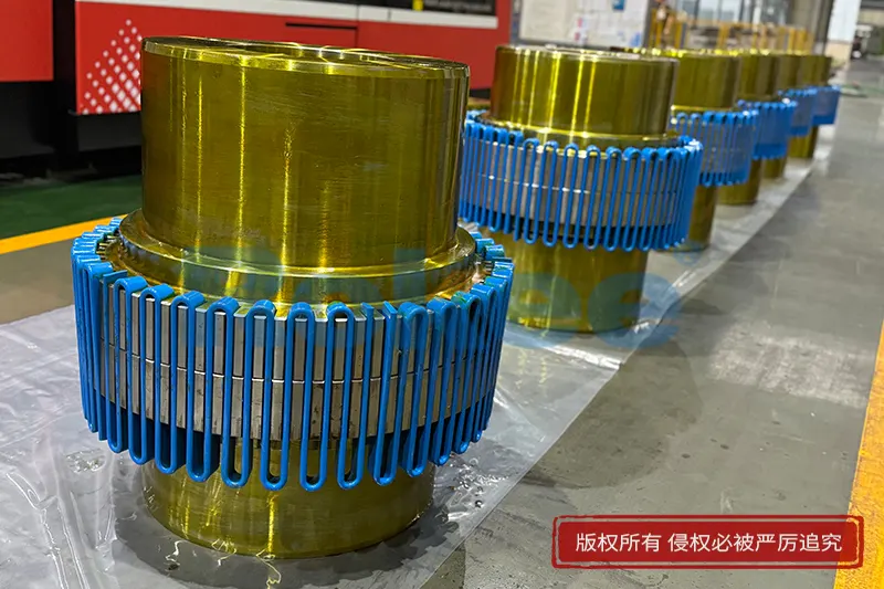
Shop high-quality Flexible Steel Grid Couplings. High torque, easy maintenance, standard & custom bore sizes. Reliable serpentine grid couplings for mining, cement & processing equipment. Rokee is a flexible steel grid couplings supplier in China. We support custom orders and offer direct factory sales, providing reliable products with flexible solutions for global clients.
Flexible steel grid couplings are mechanical transmission components that transfer torque between rotating shafts while absorbing shock and compensating for minor shaft misalignment. Constructed with steel grids, hubs, covers and seals, they transmit power through controlled elastic deformation of heat-treated steel grids. Featuring high torque density and vibration damping, they suit medium and heavy-duty equipment like pumps, conveyors and crushers. Proper alignment, lubrication and routine inspection are essential for stable service life. Selection depends on torque, speed and installation requirements.
Flexible steel grid couplings are a type of mechanical connecting component used to transmit torque between two rotating shafts while accommodating minor misalignment and absorbing shock loads. They rely on specially formed steel grids as the elastic load-bearing element to bridge the hubs mounted on the driving and driven sides. Unlike rigid couplings that provide fixed shaft connection without displacement compensation, this coupling category balances torsional flexibility and structural strength. It can buffer instantaneous impact and vibration generated during equipment operation, avoiding concentrated stress on connected shafts, bearings and seals. The overall design is compact, and the power transmission path is direct, making it widely adopted in rotary power transmission systems that require both reliable torque transfer and moderate flexibility.
Classification and Common Models
Flexible steel grid couplings are mainly sorted according to structural layout, grid installation form and allowable displacement capacity. One primary division covers horizontal split casing types and closed fully enclosed casing types. Split casing versions allow inspection and grid replacement without fully detaching the connected equipment, while enclosed casing styles offer better protection against dust, moisture and external debris. Another classification is based on the grid profile, including serpentine curved grids and straight profiled grids. Serpentine grids are the most widely used variant for general power transmission scenarios.
Common model series differ in rated torque range, shaft bore size range and outer dimension specifications. Each model group corresponds to a continuous torque capacity interval and a maximum permissible rotational speed. Larger frame sizes are designed for heavy-duty low-speed transmission, whereas smaller sizes suit light and medium load high-speed applications. Models are also differentiated by whether accessories such as lubrication fittings are pre-configured, to match different maintenance arrangements.
Structural Composition and Materials
The core assembly of a flexible steel grid coupling consists of two identical hubs, one or more steel grids, a protective cover and sealing parts. The two hubs are separately fitted onto the driving shaft and driven shaft. Grooves with matched profiles are machined on the outer circumference of each hub to hold the steel grid. The steel grid fits across the grooves of both hubs to form the torque transfer medium. The outer cover wraps around the grid and hub section, and seals are placed between the cover and hubs to retain internal lubricant and block contaminants.
High-strength alloy steel is the standard material for the steel grid, processed through heat treatment to achieve balanced hardness and toughness, resisting fatigue fracture under repeated torsional load cycles. Hubs are generally manufactured from carbon steel or cast steel, with precision machining on the groove surfaces to ensure uniform contact with the grid. Protective covers can be cast metal or fabricated steel components. Sealing elements use elastomer materials that maintain stable performance under normal operating temperature ranges. Lubricants filled inside are grease formulations suitable for sliding friction between grids and hub grooves.
Working Principle
When the driving shaft rotates, torque is transferred to the driving hub first. The hub grooves push against the embedded steel grid, and the grid then transmits rotational force to the driven hub and the connected driven shaft. Under perfect shaft alignment conditions, the grid bears evenly distributed torsional shear force. If radial, angular or axial misalignment exists between the two shafts, the steel grid will deform slightly within the clearance of the hub grooves. This controlled deformation allows the coupling to absorb displacement without generating excessive additional bending stress on the shafts.
During sudden load surges or impact events, the grid’s flexible deformation dissipates part of the shock energy. Relative sliding occurs between the grid and the groove contact surfaces, which is why continuous lubrication is required to reduce wear at the contact interfaces. Once the transient shock disappears, the grid returns to its original working state and resumes steady torque transmission.
Features and Advantages
A prominent advantage of flexible steel grid couplings is the combination of high torque density and controlled torsional flexibility. Compared with many elastomer couplings, they can carry heavier loads within a similar installation space. They also have better resistance to high temperature and aging, as their load-bearing element is metal instead of rubber or polymer materials.
These couplings can simultaneously compensate for angular, radial and axial misalignment within specified limits. Their vibration damping performance reduces the transmission of periodic mechanical vibration from the driving side to downstream equipment. The modular structure simplifies part replacement; worn grids can be changed without removing the hubs from the shafts in split casing designs. The backlash of the coupling is relatively low under normal operating conditions, which supports stable rotation for most transmission systems. The service life can be long when proper lubrication and alignment are maintained.
Meanwhile, the coupling has inherent limitations. It cannot accommodate extremely large shaft misalignment. It depends on lubrication to control wear, so regular lubrication management is mandatory. It is not ideal for applications requiring zero backlash under highly precise positioning demands.
Applicable Working Conditions and Application Industries
Suitable operating conditions include steady or periodically fluctuating torque loads, with occasional impact loading. The ambient temperature should stay within the range compatible with the selected seal and lubricant materials. The coupling works well where moderate shaft misalignment is unavoidable even after careful installation. It is not suited for environments with strong corrosive media that can erode steel components, unless additional surface protection is applied. It also should not be used under continuous heavy shock beyond its designed load capacity.
Typical application industries cover material handling, including conveyors, bucket elevators and crushers. They are commonly arranged on pumps, fans and blowers in fluid transport systems. Many general processing machinery, mixers, agitators and rotary drying equipment adopt this coupling type. It is also found in auxiliary transmission systems of metallurgical processing equipment, timber processing machinery and mining auxiliary equipment.
Installation and Commissioning Points
Before installation, all components are inspected to check for mechanical damage, deformation or burrs on hub grooves and grids. Shaft surfaces and hub bores are cleaned thoroughly. Hubs are mounted onto the driving and driven shafts, usually secured by locking assemblies or key connections. The spacing between the two hub end faces is adjusted to the dimension required for the selected model.
Alignment is the most critical step. Radial offset and angular deviation between the two shafts must be adjusted to stay within the allowable range. Excessive misalignment will accelerate grid wear and lead to premature failure. After alignment, the steel grid is placed into the paired hub grooves, then the protective cover and sealing parts are assembled. Lubricant is filled into the internal cavity following the recommended filling amount.
During commissioning, the equipment is first run without load for a short period. Operators check for abnormal noise, vibration or lubricant leakage. The running temperature of the coupling area is monitored. If abnormal vibration or noise occurs, the unit is shut down promptly to recheck alignment, grid assembly and sealing status. Load can be gradually applied only after no abnormal conditions are observed in no-load operation.
Selection and Customization
Selection starts with defining core operating parameters, including continuous operating torque, peak torque from shock loads, operating speed, shaft diameters of driving and driven equipment, and available installation space. The required misalignment compensation capacity is also confirmed. The basic model is initially chosen according to the maximum torque and speed. A service factor is applied to account for load fluctuation and impact characteristics of the driven machine to avoid overstressing the coupling.
Shaft bore dimensions, keyway specifications and hub length can be customized to match the actual shaft dimensions of user equipment. Surface treatment options for hubs and covers can be adjusted for improved corrosion resistance. Special grid materials or modified sealing structures can be provided for non-standard ambient temperature environments. Customized cover designs may be offered to fit limited installation space. All customized parameters need to match the torque and speed rating of the base coupling frame to maintain safety and performance.
Operation and Maintenance
Routine maintenance focuses mainly on lubrication condition and alignment status. Periodic inspections are arranged to check for lubricant leakage from the seal positions. Lubricant replenishment or replacement is carried out on the scheduled cycle; high-frequency start-stop and heavy-load conditions require shorter lubrication intervals.
Regular visual inspection can be performed by removing the split cover where applicable, to check grid surface wear, cracks or permanent deformation. If the grid shows obvious thinning at contact points, fatigue cracks or deformation, it must be replaced in time. Hubs are checked for groove wear and corrosion. Seals are replaced when aging or leakage appears.
After equipment overhaul or relocation, shaft alignment must be re-verified. If abnormal vibration, sharp noise or temperature rise emerges during operation, the system should be stopped for inspection. Preventive replacement of wearing parts helps avoid unexpected breakdown. Records of inspection, lubrication and part replacement help track the working state and predict maintenance cycles.