Grid Flex Couplings
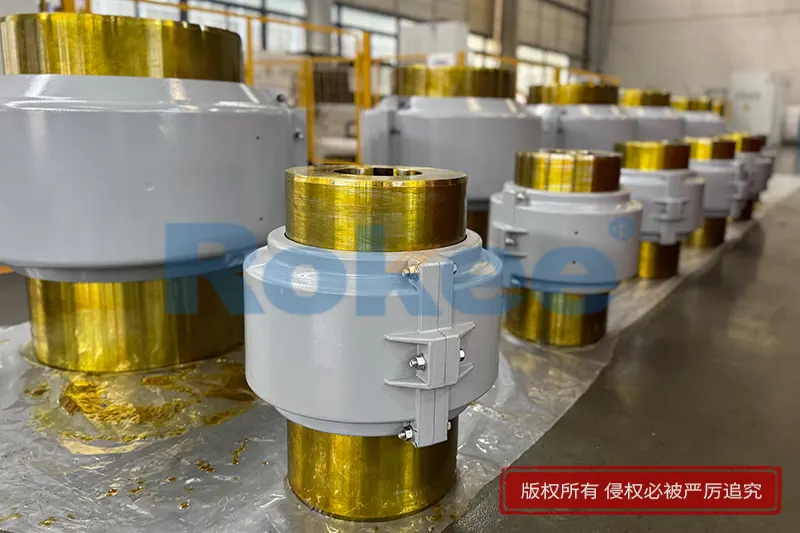
Grid Flex Couplings for industrial power transmission. Absorb shock, damp vibration & accommodate shaft misalignment. High torque steel grid couplings for pumps, conveyors & heavy machinery. Standard & custom bore sizes. Rokee is a grid flex couplings supplier in China. We support custom orders and offer direct factory sales, providing reliable products with flexible solutions for global clients.
Grid flex couplings are flexible shaft connectors that transmit torque while absorbing shock, damping vibration and accommodating combined shaft misalignment. Main types include split cover, solid cover, close-coupled, spacer and floating shaft versions. They mainly consist of steel hubs, a serpentine spring steel grid, protective covers and seals. Torque transfers through the grid’s controlled elastic deformation. Featuring high torque density and progressive stiffness, they serve pumps, conveyors and processing machinery. Proper alignment, lubrication and routine inspection are essential for reliable operation.
Grid flex couplings are a type of flexible power transmission component designed to connect two rotating shafts while accommodating misalignment, absorbing vibration and mitigating shock loads during operation. They serve as a compliant link between driving and driven equipment, bridging the gap between rigid couplings that offer no tolerance for positional deviation and highly elastic couplings with limited torque capacity. This coupling family balances torsional flexibility and structural robustness, making it a versatile solution for general and heavy-duty rotary power transmission. The core design concept relies on a resilient grid element to transmit torque and deliver controlled flexibility, rather than depending on rubber blocks, elastomer sleeves or gear tooth meshing for compliance.
Classification and Common Types
Grid flex couplings can be grouped according to structural layout and assembly form. The primary categories include horizontal split grid couplings and solid cover grid couplings. Horizontal split variants feature separable housing covers that allow inspection, replacement of the grid element and alignment checks without fully detaching the coupled equipment. Solid cover types provide full enclosure for enhanced protection against contaminants and debris, and are typically used in environments with heavy airborne particles.
Common configurations cover basic close-coupled styles for compact shaft spacing, spacer types for applications with a large distance between the driving and driven hubs, and floating shaft designs for long span transmission setups. Each configuration follows the same fundamental grid-based flexing principle and is modified only to adapt to different shaft separation requirements.
Structural Composition and Materials
A standard grid flex coupling assembly consists of four major parts: two mating hubs, a spring grid, a protective cover set and sealing accessories. The hubs are mounted onto the respective input and output shafts, with pre-machined curved grooves distributed circumferentially on their outer surfaces to hold the grid. The spring grid is formed from a single continuous strip of spring material, bent into a repeating serpentine profile that seats within the interlocking grooves of the paired hubs. The cover assembly wraps around the grid to retain lubricant and block foreign matter. Seals fit between the cover and hubs to reduce lubricant leakage and ingress of dirt.
Hub materials are usually high-strength carbon or alloy steel, selected for good machinability and resistance to torsional stress. The grid element is manufactured from heat-treated spring steel to maintain consistent elastic performance after repeated flexing cycles. Cover components may use cast metal or formed steel plate. Sealing elements are formulated from synthetic elastomers compatible with common lubricants and a wide temperature range.
Working Principle
Torque transfer begins when the driving hub rotates, and the side walls of its grooves push against the embedded segments of the serpentine grid. The grid then transfers the rotational force to the corresponding groove surfaces on the driven hub. When shaft misalignment, shock or torsional vibration occurs, the curved segments of the steel grid deform slightly in a controlled manner. This elastic deformation creates the coupling’s flexibility, allowing it to accept parallel, angular and axial misalignment simultaneously.
Unlike rigid transmission interfaces, the grid does not lock completely. Under shock loading, the grid yields marginally to cushion sudden torque spikes before returning to its original shape once the transient load subsides. Lubricant inside the cover fills the clearance between the grid and groove surfaces, reducing friction and wear as the grid flexes and slides minimally within the grooves during misalignment movement.
Features and Advantages
Grid flex couplings combine medium torsional flexibility with high torque density. They can handle substantially higher continuous torque than many elastomer couplings of the same outer dimension, while retaining the ability to damp shock and vibration. Their flexibility is progressive: stiffness rises gradually as transmitted torque increases, which helps stabilize system resonance characteristics in many rotating machines.
The split cover design on many models simplifies routine inspection and grid replacement, without requiring full disconnection of the connected machinery. The single-piece grid reduces the risk of fragmentation common in multi-part flexible inserts. Compared with gear couplings, they generate lower backlash and run quieter under steady operation. They also offer better tolerance for combined forms of misalignment than rigid disc couplings. When properly lubricated, the grid has a long service life under steady load conditions.
Applicable Conditions and Industry Applications
These couplings are suited for equipment with moderate to high torque, where some degree of shaft misalignment is unavoidable and shock or impulse loads may occur intermittently. They perform well in continuous steady-speed operation, and can accommodate cyclic load fluctuations as long as peak torque stays within the working range of the grid element. Extended exposure to strong corrosive media or extreme high temperatures beyond the material limits of the grid, seal and lubricant will shorten service life and should be avoided unless special material selections are made.
Typical application fields include material handling machinery, conveyors, fans and blowers, pumps, compressors, mixers and agitators, as well as general industrial processing equipment. They are also widely used on prime mover drives connected to reduction gearboxes in heavy processing plants.
Installation and Commissioning Points
Before installation, the shaft surfaces, hub bores and keyways should be cleaned thoroughly to remove burrs, rust and residual machining debris. Hubs are fitted onto shafts with proper interference or clearance matching according to the mounting method, and secured using keys, set screws or clamping fasteners as appropriate. The two hubs must be positioned to maintain a correct gap between their facing ends; excessive gap or insufficient gap will disrupt grid engagement and reduce misalignment capacity.
Shaft alignment is critical. Both angular and parallel offset must be adjusted to stay within the allowable limits of the coupling. After rough alignment, preliminary hand rotation of the assembly can identify binding or uneven resistance. Once alignment is confirmed, the grid is seated into the interlocking grooves, followed by fitting the cover and seals. Lubricant is added to the internal cavity before the cover is fully fastened. After commissioning, the unit should be run at low speed for a short period and rechecked for abnormal noise, leakage or temperature rise before moving to full operating speed.
Selection and Customization
The primary selection basis is the normal operating torque, together with anticipated peak shock torque and rotating speed. Service factor is applied to account for load impulsiveness of the connected equipment. The maximum allowable misalignment values, shaft diameters and the separation distance between shafts are also key parameters for choosing the coupling configuration.
Customization options mainly cover bore size and keyway configuration to match non-standard shaft dimensions. Special material alternatives can be provided for hubs, grids and seals to adapt to challenging ambient conditions. Spacer length can be modified to fit fixed centre distances between equipment. Changes to surface treatment are available where extra resistance to atmospheric corrosion is required. Custom designs do not alter the fundamental grid flex operating principle.
Operation and Maintenance
Periodic maintenance focuses primarily on lubrication condition and grid integrity. Regular scheduled checks should look for lubricant leakage at the seal points, unusual operating noise and excessive temperature at the coupling housing. Lubricant should be replenished or replaced at specified intervals, as degraded lubricant accelerates wear between the grid and hub grooves.
When abnormal vibration appears after a period of operation, shaft alignment should be re-verified first. If the grid shows signs of fatigue cracking, permanent deformation or surface wear, it must be replaced promptly. Hubs should be inspected for groove wear or damage during grid replacement. Preventive maintenance reduces the chance of sudden coupling failure that could disrupt the whole drive train. Disassembly for inspection should only be carried out after the connected equipment is fully stopped and locked out from power input.