Spider Couplings

High-quality spider couplings direct from manufacturer. Compact jaw coupling with replaceable spider insert. Fast delivery, custom bores & bulk pricing for industrial power transmission projects. Rokee is a spider couplings supplier in China. We support custom orders and offer direct factory sales, providing reliable products with flexible solutions for global clients.
Spider couplings are popular elastomeric flexible couplings for torque transmission between rotating shafts. Composed of two jaw hubs and a spider-shaped elastic insert, they transfer torque via compression of the insert and compensate for minor angular, parallel and axial misalignment. They damp vibration and absorb shocks, featuring compact structure and easy assembly. Widely used for pumps, conveyors and packaging machinery under moderate loads, they require careful alignment and regular inspection of the consumable elastomer insert for stable operation.
-
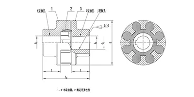
LM Plum Blossom Coupling
Basic Standard
LM/ML plum coupling is a basic standard jaw coupling, simple structure, easy installation and maintenance, good vibration damping performance. -
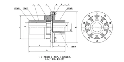
LMD Plum Blossom Coupling
Single flange
The LMD/MLZ single flange plum coupling is equipped with a transition connection. The elastic spider can be replaced without axial movement of the coupling halves. -
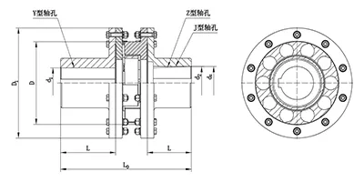
LMS Plum Blossom Coupling
Double flange
The LMS/MLS plum coupling adopts double transition flange connection. The elastic spider can be replaced without axial movement of the coupling halves. -
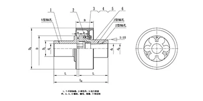
LMZ-I Plum Blossom Coupling
Split type with brake wheel
The LMZ‑I/MLL-I plum coupling adopts a split brake wheel design, suitable for braking applications. -
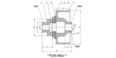
LMZ-II Plum Blossom Coupling
Integrated type with brake wheel
The LMZ‑II/MLL-II plum coupling adopts an integrated brake wheel design and is suitable for braking applications. -
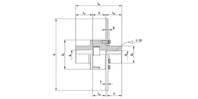
LMPK Plum Blossom Coupling
split construction with brake disc
The LMPK/MLPK plum coupling adopts a split brake disc design, suitable for braking occasions. The elastic element can be replaced without axially moving the coupling half.
Spider couplings are a widely used type of flexible shaft coupling designed to transmit torque between two rotating shafts while accommodating minor misalignment. They belong to the elastomeric coupling family and rely on a resilient insert to deliver flexible connection. The name originates from the spider-shaped elastic element at the core, which sits between two metallic hub halves. This coupling type balances simplicity and damping performance, making it a mainstream choice for general power transmission systems. It connects driving and driven equipment, buffers vibration, and reduces shock loads generated during start-up, speed fluctuation and sudden load changes. Unlike rigid couplings, it does not demand perfect shaft alignment, which lowers the assembly difficulty for most rotating machinery.
Classification and Common Models
Spider couplings can be grouped according to structural layout and the shape of the elastic spider insert. The primary categories include the standard straight-jaw type, curved-jaw type, split-hub type and clamping type. Straight-jaw variants feature rectangular contact surfaces on the hub jaws and are suitable for steady load conditions. Curved-jaw designs have arc-shaped contact profiles that allow larger angular misalignment and produce lower contact stress on the elastomer. Split-hub spider couplings permit installation or removal without fully displacing the connected equipment, which facilitates maintenance in compact spaces. Clamping hub versions use friction locking instead of keyway connection for shaft mounting.
Common model series follow conventional dimensional frameworks differentiated by torque capacity and bore range. Each model corresponds to a defined maximum transmitting torque and outer dimension. Different insert hardness options are normally offered within the same model series to adjust damping and load resistance. Model selection is primarily bounded by rated torque, shaft diameter and allowable misalignment rather than standardized marking rules.
Structural Composition and Materials
A complete spider coupling assembly consists of three core parts: two identical jaw hubs and one elastomeric spider insert. Each jaw hub is machined with multiple protruding jaws distributed evenly around its end face. The lobes of the spider insert fit tightly into the gaps between jaws from the two hubs, interlocking the driving hub and driven hub together. Some configurations may include optional protective covers to prevent dust contamination and accidental contact with rotating components.
Jaw hubs are commonly manufactured from carbon steel or cast iron. Carbon steel hubs feature higher strength and better impact resistance for heavy-duty cyclic loads, while cast iron hubs are adopted for light and medium load applications where cost stability and good machinability are preferred. The spider insert is the flexible component, and the most popular base materials are polyurethane and rubber. Polyurethane inserts show outstanding wear resistance, high load capacity and low permanent deformation. Rubber inserts deliver superior vibration damping and noise absorption, suitable for noise-sensitive operating environments.
Working Principle
Torque transmission depends on mechanical compression of the spider insert. When the driving shaft rotates, the jaws on the driving hub press against the lobes of the elastic spider. The insert transfers the compressive force to the jaws of the driven hub, and subsequently drives the driven shaft to rotate synchronously. The elastomeric spider acts as a compliant intermediate medium.
When parallel, angular or axial misalignment exists between the two shafts, the lobes of the spider undergo controlled elastic deformation. This deformation absorbs positional deviation without generating excessive additional bending stress on the shafts and bearings. Under shock or pulsating load, the elastic material deforms temporarily to store and release energy, so as to attenuate peak impact loads and isolate vibration transfer from the driving side to the driven side. The insert only works under compression during normal operation; tensile stress should be avoided to extend service life.
Features and Advantages
Spider couplings combine multiple practical merits. First, they can compensate for three basic forms of shaft misalignment within a permissible range: angular misalignment, parallel offset and limited axial displacement. Second, the elastomeric insert provides effective vibration damping and shock absorption, suppressing resonant vibration in many transmission systems. Third, the overall structure is compact with small radial dimensions and low weight, fitting well in confined installation envelopes.
Assembly and disassembly are straightforward. No special tools are required for routine replacement of the spider insert, and hubs can remain on the shafts during insert replacement. The coupling runs with low noise under normal operating conditions. It also exhibits good tolerance to occasional overload within a short duration. Compared with many other flexible couplings, the design has fewer components and fewer failure points. One inherent limitation is that the elastomer is a consumable part and will degrade gradually under heat, oil and continuous cyclic loading.
Applicable Conditions and Application Industries
Spider couplings adapt to steady or moderately fluctuating torque loads and continuous rotation at medium and low to moderate rotational speeds. They are not recommended for scenarios with extreme high temperature, strong chemical corrosion, continuous heavy shock or ultra-high speed operation. The working temperature range is restricted by the material of the spider insert. Long-term exposure to grease, solvent and ultraviolet radiation will accelerate aging of the elastic element.
They are extensively deployed in general industrial power transmission. Typical application fields include material handling equipment, conveyor systems, fans and blowers, water pumps, packaging machinery, textile equipment, machine tool auxiliary drives and light mixing equipment. They are also widely matched with gear reducers and small and medium electric motors. In these equipment, the coupling connects motor output shafts and reducer input shafts, or links reducers to final working actuators.
Installation and Commissioning Guidelines
Before installation, inspect hubs and the spider insert for cracks, deformation or surface damage. Clean shaft surfaces, keyways and inner bore holes to remove burrs, rust and residual oil. Mount the two jaw hubs onto the driving and driven shafts respectively. Proper axial spacing between the two hubs must be maintained to avoid direct metal contact between jaws and reserve space for thermal expansion and axial movement.
Alignment is the critical step. Adjust the position of connected equipment to reduce shaft misalignment as much as possible. Excessive misalignment will sharply raise the compression load on the spider insert, accelerate wear and cause premature failure. After alignment, secure the hubs axially. For keyed connections, ensure proper key fit; for clamping hubs, tighten clamping fasteners to appropriate tightness. Insert the spider lobes into the jaw gaps evenly and check that all lobes are fully seated without twisting.
After mechanical assembly, perform a no-load trial run first. Monitor for abnormal noise, vibration and temperature rise at the coupling position. Stop operation immediately if irregular phenomena occur and recheck alignment and assembly state before putting the system under load.
Selection and Customization
The core basis for coupling selection is the calculated operating torque, which takes into account nominal torque and load fluctuation characteristics of the transmission system. The maximum continuous torque and starting peak torque must stay below the load limit of the chosen coupling. Next, confirm shaft diameters of the driving and driven ends to match the bore size of hubs. The allowable misalignment requirement, rotating speed and ambient environment should also be evaluated.
When standard options cannot satisfy requirements, customized solutions are available. Customizable items include special bore dimensions, non-standard keyway forms, modified hub lengths, special surface treatment for hubs and alternative elastomer formulations for the spider insert. Customization is usually targeted at unique space constraints, special environmental conditions or non-standard shaft connection structures. After customization, the torque capacity and misalignment allowance of the modified coupling should be re-evaluated to match the working condition.
Operation and Maintenance
Regular visual inspection is the main maintenance measure. Check the spider insert periodically for cracking, chipping, swelling, hardening or permanent deformation. Once obvious damage is found, replace the insert promptly. Inspect hub jaws for wear and check whether hubs become loose on the shafts.
Avoid prolonged operation beyond the allowable temperature range and prevent direct contact between the elastomer insert and harmful liquid or chemical medium. If leakage of lubricant from adjacent components contaminates the spider, clean the contaminated area or replace the insert if swelling has happened. Record the running state and replacement cycle of the elastic insert to establish a reasonable maintenance schedule.
When replacing the spider insert, shut down the power source completely and confirm the system is static. Do not attempt replacement while equipment is rotating. After replacement, repeat alignment verification and no-load test. The service life of the insert depends heavily on alignment quality, load cycle, operating temperature and chemical environment. Good alignment control can greatly extend the service interval of the coupling.