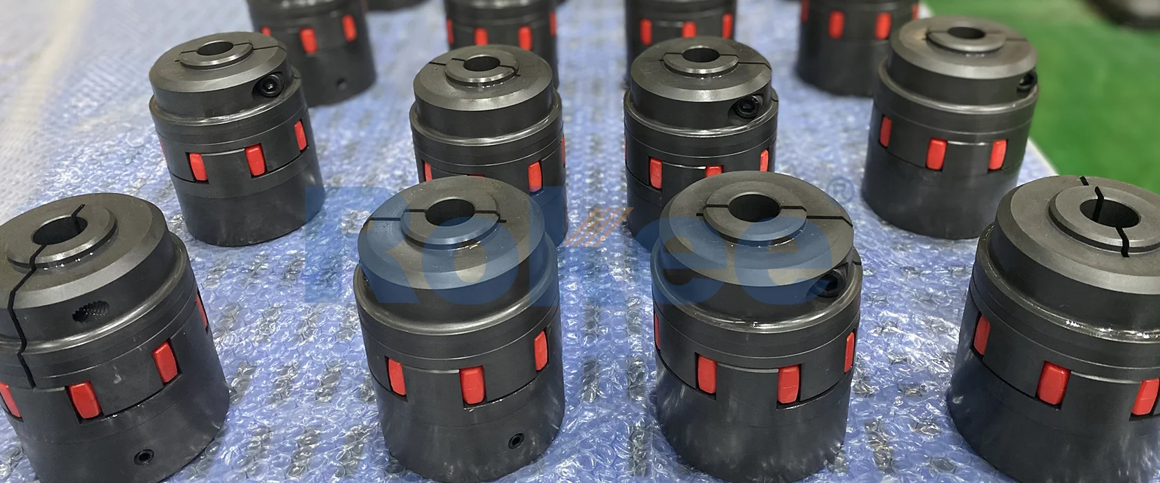
Rokee is a well-known high-quality supplier of Claw Couplings and technical services in China, customize claw couplings according to user drawings, alternatively, if the user provides claw couplings parameters, we can select the model and design drawings for you, support wholesale and export.
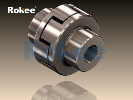
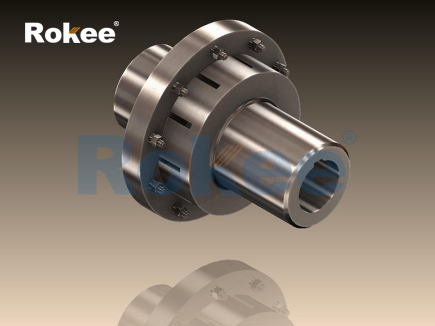
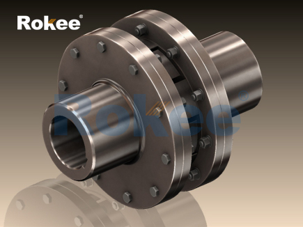
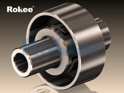
Claw coupling is a common mechanical transmission component and a deformation structure of rigid coupling. It achieves power transmission between two shafts through a specially designed "claw shaped" concave convex meshing structure, combining the dual characteristics of high transmission accuracy of rigid couplings and partial compensation capability of flexible couplings.
Basic components
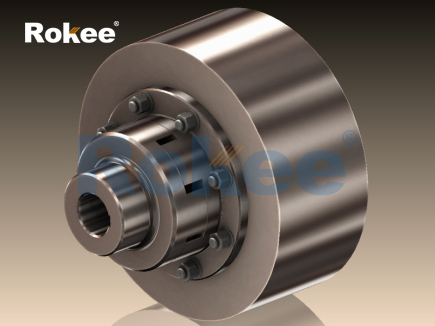
A typical claw coupling consists of the following core components:
Two half couplings: installed on the driving shaft and the driven shaft respectively, with interlocking claw teeth machined on the end faces
Intermediate isolation ring: located between two half couplings, usually made of elastic material
Tightening bolt: used to fix the connection between the coupling and the shaft
Protective cover (optional): Safety protection device
Geometric features of claw teeth
The geometric parameters of the claw teeth directly affect the performance of the coupling:
Number of teeth: usually 6-12, odd tooth design can avoid simultaneous meshing
Tooth shape: There are three common types: trapezoidal, circular arc, and involute
Mesh angle: generally designed as a contact slope of 30 ° -45 °
Tooth tip clearance: Maintain a radial clearance of 0.1-0.3mm
Power transmission mechanism
Claw couplings transmit torque through the following methods:
The rotation of the active shaft drives the rotation of the half coupling
The inclined surfaces of the claw teeth come into contact with each other, generating a normal force
The tangential component of the normal force forms the driving torque
The driven half coupling rotates synchronously under the action of torque
Unique mechanical properties
Torque transmission capability: positively correlated with tooth friction coefficient and normal pressure
Impact resistance characteristics: The elastic isolation ring can absorb some vibration energy
Self centering ability: The helical tooth design allows for small angular deviations (usually ≤ 1 °)
Overload protection: When the torque exceeds the design value, the claw teeth can slip and disengage
significant advantage
Compact structure: small axial size, saving installation space
Maintenance free design: No lubrication required, long service life
Buffer vibration reduction: superior to pure rigid couplings
Electrical insulation: non-metallic type can isolate stray currents
Cost effectiveness: Price lower than gear couplings of the same specifications
Usage restrictions
Limited compensation capability, not suitable for large deviation situations
Noise may be generated during high-speed operation
The overload protection function is not as reliable as the safety coupling
Elastic components have aging issues
Transmission power and speed
Axis diameter size matching
Environmental conditions (temperature, corrosiveness, etc.)
Installation space restrictions
Expected median error
Do you need electrical insulation
Correct installation process
Clean the shaft end and coupling inner hole
Install using hot installation or hydraulic method to avoid hammering
Check the alignment using a dial gauge
Gradually tighten the bolts to the specified torque
Install protective cover (if any)
Maintenance Recommendations
Regularly check the tightening status of bolts
Monitor vibration and noise changes
Check the aging condition of elastic components
Keep the coupling clean and avoid oil accumulation
Suggest conducting a comprehensive inspection every 2 years
Pump equipment: centrifugal pump, plunger pump, etc
Compressor system: air compressor, refrigeration compressor
Power generation equipment: small generators, wind power yaw systems
Material conveying: conveyor belt, screw conveyor
Food and pharmaceutical machinery: plastic claw couplings that meet hygiene requirements
Automation equipment: robotic arms, CNC machine tool feed systems
With the development of industry, claw couplings are evolving towards high performance, intelligence, and customization, and will play a more important role in the field of precision transmission.
In the complex network of mechanical power transmission systems, couplings serve as the critical link that bridges rotating shafts, ensuring the smooth transfer of torque while accommodating inevitable misalignments and mitigating operational vibrations. Among the diverse range of coupling types available, the claw coupling stands out as a versatile and widely adopted solution, valued for its balanced combination of simplicity, reliability, and cost-effectiveness. Designed to meet the demands of various industrial environments, from light-duty automation equipment to heavy-duty processing machinery, claw couplings have established themselves as indispensable components in modern mechanical engineering. Their unique structural design, which integrates rigid metal components with flexible elastomers, enables them to perform multiple functions simultaneously: transmitting torque efficiently, absorbing vibrations, compensating for shaft misalignments, and providing a degree of overload protection.
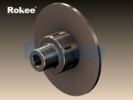
At the core of a claw coupling lies a straightforward yet ingenious structural design, consisting of three primary components: two metal half-couplings (often referred to as claw discs or hubs) and a central flexible element. This modular structure is engineered to balance the need for robust torque transmission with the flexibility required to adapt to dynamic operational conditions. The two metal half-couplings form the backbone of the coupling, serving as the interface between the driving and driven shafts. Each half-coupling features a series of evenly distributed convex claws on one end, which are precision-machined to ensure a tight and uniform engagement with the flexible element. The number of claws typically ranges from 3 to 12, with 6 being the most common configuration, as it offers an optimal balance between torque capacity, stress distribution, and manufacturing simplicity. The claws can be designed with various cross-sectional profiles, including straight, curved, or composite surfaces, each tailored to specific performance requirements. Straight claws are the most basic design, easy to manufacture and suitable for general-purpose applications, while curved claws provide a larger contact area with the flexible element, resulting in improved load-bearing capacity and smoother torque transmission. Composite surface claws, which combine curved and flat sections, are engineered to distribute stress more evenly across the entire engagement area, reducing the risk of localized wear and extending the service life of both the claws and the flexible element.
The material selection for the metal half-couplings is a critical factor that directly influences the coupling’s torque capacity, durability, and weight. High-strength metals are preferred to withstand the rotational forces and stresses encountered during operation. Carbon steel, particularly medium-carbon grades, is a common choice due to its excellent mechanical properties, including high tensile strength, good wear resistance, and affordability. These steels are often heat-treated to enhance their hardness and toughness, ensuring they can handle medium to high torque loads without deformation or failure. For applications where weight reduction is a priority, such as in portable machinery or high-speed systems where rotational inertia must be minimized, aluminum alloys are frequently used. Aluminum alloys offer a favorable strength-to-weight ratio, corrosion resistance, and good thermal conductivity, though their torque capacity is generally lower than that of carbon steel. In environments where corrosion resistance is paramount, such as chemical processing plants or marine applications, stainless steel may be employed, despite its higher cost, to prevent rust and degradation over time. The half-couplings are typically manufactured using precision machining processes, including turning, milling, and broaching, to ensure tight dimensional tolerances and a smooth surface finish. This precision is essential for achieving proper alignment between the claws and the flexible element, which directly impacts the coupling’s performance and longevity.
The central flexible element, often called the spider or plum-shaped insert due to its typical configuration, is the heart of the claw coupling’s vibration-damping and misalignment-compensation capabilities. This element is crafted from non-metallic, elastic materials that can deform under load and then return to their original shape, allowing it to absorb vibrations and accommodate relative displacements between the two shafts. The choice of material for the flexible element is determined by the specific operating conditions of the application, including temperature range, torque requirements, exposure to chemicals or oils, and desired vibration absorption properties. Polyurethane is the most widely used material for these elements, offering an excellent balance of flexibility, wear resistance, tear resistance, and oil resistance. It is available in a range of hardness levels, from soft to rigid, allowing engineers to tailor the coupling’s performance to the application—softer polyurethane provides superior vibration damping, while harder grades offer higher torque capacity and durability. Nitrile rubber (NBR) is another popular option, particularly in applications where exposure to lubricating oils is common, as it exhibits excellent oil resistance. However, NBR has lower temperature resistance compared to polyurethane, making it less suitable for high-temperature environments. Engineering plastics such as nylon (polyamide) are used for applications requiring higher rigidity and dimensional stability, though they offer less vibration absorption than rubber or polyurethane. For specialized high-performance applications, polyester elastomers may be employed, providing exceptional strength, fatigue resistance, and suitability for high-speed operations. The flexible element is typically designed with lobes that correspond to the number of claws on the half-couplings, ensuring a precise interlock that enables efficient torque transmission while maintaining flexibility.
The working principle of a claw coupling is rooted in the interaction between its rigid and flexible components, leveraging mechanical meshing and elastic deformation to achieve reliable power transmission. When the driving shaft rotates, it imparts rotational force to the corresponding half-coupling. The claws of this active half-coupling exert compressive force on the lobes of the flexible element, which in turn transfers this force to the claws of the passive half-coupling connected to the driven shaft. This transfer of force occurs through the elastic deformation of the flexible element, which acts as a buffer between the two rigid half-couplings. Unlike rigid couplings, which require perfect alignment between shafts and transmit all vibrations and misalignments directly, claw couplings use the flexibility of the central element to absorb vibrations generated by the driving shaft or by operational inconsistencies. This vibration-damping capability is crucial for protecting sensitive components in the transmission system, such as bearings, seals, and gears, from excessive wear and premature failure. Additionally, the elastic deformation of the flexible element allows the coupling to compensate for three types of shaft misalignment: axial, radial, and angular. Axial misalignment occurs when the shafts are displaced along their common axis, radial misalignment when the shafts are offset parallel to each other, and angular misalignment when the shafts are tilted relative to one another. The degree of compensation possible varies depending on the design of the coupling, the material of the flexible element, and the number of claws, but typical ranges include axial deviation of ±0.5 to 3 mm, radial deviation of 0.2 to 1.5 mm, and angular deviation of 0.5° to 3°. This compensation capability reduces the mechanical stress on the shafts and connected equipment, improving overall system stability and extending service life.
One of the key advantages of claw couplings is their ability to provide backlash-free transmission under normal operating conditions. Backlash, or the clearance between mating components, can lead to imprecise positioning, increased noise, and shock loads when the direction of rotation changes. The tight interlock between the claws of the half-couplings and the lobes of the flexible element eliminates this clearance, ensuring smooth and precise torque transmission even during frequent start-stop cycles and reverse operations. This feature makes claw couplings particularly suitable for applications requiring high positional accuracy, such as CNC machine tools, robotics, and automated packaging equipment. Another significant benefit is their maintenance-free design. Unlike gear couplings or universal joints, which require regular lubrication to prevent wear and corrosion, claw couplings do not need lubrication due to the self-lubricating properties of their non-metallic flexible elements. This reduces maintenance costs, minimizes downtime, and simplifies the overall operation of the equipment. Additionally, claw couplings offer a degree of overload protection. When the torque exceeds the design limit of the coupling, the flexible element will deform excessively or fail before any damage occurs to the more expensive shafts, motors, or other components. This sacrificial nature of the flexible element acts as a safety mechanism, preventing costly repairs and downtime in the event of an overload.
Claw couplings are available in a variety of variant types, each designed to meet the specific needs of different applications. The most common variants are categorized based on claw design, flexible element configuration, and mounting style. Straight-claw couplings are the basic type, featuring simple, linear claws that are easy to manufacture and cost-effective. They are suitable for general-purpose applications with moderate torque requirements and minimal misalignment. Curved-claw couplings, also known as concave-claw couplings, have claws with a curved profile that provides a progressive contact with the flexible element. This design reduces stress concentrations, allows for smoother torque transmission, and offers improved misalignment compensation compared to straight-claw models. Multi-claw couplings, which feature more than 8 claws, distribute torque across a greater number of contact points, increasing torque capacity and reducing wear on individual lobes of the flexible element. These are often used in heavy-duty applications such as mining equipment, pumps, and compressors. Zero-backlash claw couplings are a specialized variant designed for high-precision applications, such as servo motor systems and positioning mechanisms. They feature a tighter fit between the claws and the flexible element, often achieved through a press-fit or interference fit, to eliminate any potential clearance and ensure maximum positional accuracy. Split-claw couplings are another practical variant, featuring a split half-coupling design that allows for easy installation and removal without the need to disassemble the connected shafts. This is particularly useful for large equipment or systems where shaft disassembly is time-consuming or impractical.
The versatility of claw couplings is reflected in their wide range of applications across numerous industries. In industrial automation, they are extensively used in CNC machine tools, machining centers, engraving machines, and robotic arms, where precise torque transmission and vibration damping are essential for maintaining dimensional accuracy and operational stability. In the pump and compressor industry, claw couplings are a popular choice for connecting motors to centrifugal pumps, gear pumps, screw compressors, and reciprocating compressors. The vibration absorption and misalignment compensation capabilities of these couplings help to reduce noise, extend the life of pump bearings and seals, and ensure consistent fluid flow rates. In the textile industry, they are used in spinning machines, weaving machines, and dyeing equipment, where they accommodate the slight misalignments that can occur due to thermal expansion of shafts and reduce vibrations that could affect fabric quality. The agricultural sector also benefits from claw couplings, which are employed in tractors, harvesters, and irrigation systems. These couplings can withstand the harsh operating conditions of agricultural environments, including dust, dirt, and occasional impacts, while providing reliable power transmission to various implements. In the food and pharmaceutical industries, claw couplings with food-grade elastomers are used to maintain hygiene standards, as they are resistant to cleaning agents and do not contaminate the production process. Additionally, they find applications in ventilation systems, where they connect motors to fans, reducing vibration transmission to the building structure and improving the efficiency of air circulation.
Proper installation and maintenance are essential for ensuring the optimal performance and longevity of claw couplings. The installation process begins with the careful preparation of the shafts, including cleaning the shaft surfaces to remove dirt, rust, and oil, which can affect the fit between the coupling and the shafts. The shafts must be aligned within the coupling’s compensation limits before installation, as excessive misalignment can lead to premature wear of the flexible element and increased stress on the shafts and bearings. Alignment can be performed using tools such as dial indicators or laser alignment systems, which provide precise measurements of axial, radial, and angular misalignment. Once the shafts are aligned, the half-couplings are mounted onto the shafts using one of several common fixing methods. Top set screws are the simplest and most cost-effective method, where screws are tightened against the shaft to secure the half-coupling. However, this method may cause indentations on the shaft and is less suitable for high-torque or high-speed applications. Clamping (compression) sleeves provide a more secure fit, distributing the clamping force evenly around the shaft without causing damage, making them ideal for high-precision and high-speed applications. Keyway connections, which use a key inserted into slots on both the shaft and the coupling, provide excellent torque transmission capability and are commonly used in heavy-duty applications. After mounting the half-couplings, the flexible element is inserted between the claws, ensuring that it is properly seated and aligned with all claws. The two half-couplings are then secured together using bolts, which are tightened to the recommended torque to maintain the correct preload and prevent relative movement.
While claw couplings are designed to be maintenance-free in terms of lubrication, regular inspection is still necessary to detect potential issues before they lead to failure. Routine inspections should include checking the flexible element for signs of wear, cracking, or deformation, as these are the most common indicators of impending failure. The elastomer may degrade over time due to exposure to heat, chemicals, or mechanical stress, so it should be replaced if any damage is detected. The bolts connecting the half-couplings should be checked periodically for tightness, as vibration can cause them to loosen over time. Loose bolts can lead to misalignment, increased noise, and damage to the coupling components. Additionally, the shafts and bearings should be inspected for signs of excessive wear or damage, which may indicate misalignment or overload conditions. When replacing the flexible element, it is important to select a replacement made from the same material and hardness as the original, as using a different material can alter the coupling’s performance characteristics. For example, replacing a polyurethane element with a rubber element may reduce the coupling’s torque capacity and oil resistance, while using a harder elastomer may decrease vibration damping capabilities. In environments with extreme temperatures or chemical exposure, more frequent inspections are recommended to monitor the condition of the flexible element and ensure it remains suitable for the operating conditions.
Despite their robust design, claw couplings can experience failure due to various factors, most of which are related to improper selection, installation, or maintenance. Understanding common failure modes and their causes can help in preventing unexpected downtime and reducing repair costs. One of the most common failure modes is the wear or tearing of the flexible element. This can be caused by excessive misalignment, which places uneven stress on the elastomer, leading to localized wear and eventual tearing. Overload conditions can also cause the flexible element to fail, as the elastomer is unable to withstand the excessive compressive force. Exposure to extreme temperatures can degrade the elastomer material, making it brittle (at low temperatures) or soft (at high temperatures), reducing its strength and flexibility. Chemical exposure, such as contact with oils, solvents, or cleaning agents, can also cause the elastomer to swell, crack, or lose its elastic properties. Another common failure mode is the deformation or breakage of the metal claws. This typically occurs due to severe overload, where the torque exceeds the structural capacity of the claws, or due to improper installation, such as overtightening the bolts or using mismatched components. Loose bolts can lead to relative movement between the half-couplings, causing impact loads on the claws and resulting in fatigue failure over time. Corrosion of the metal half-couplings, particularly in harsh environments, can weaken the claws and eventually lead to breakage.
To mitigate these failure modes, several preventive measures can be implemented. Proper coupling selection is critical, ensuring that the coupling’s torque capacity, speed rating, and misalignment compensation limits match the requirements of the application. Engineers should consider factors such as operating temperature, chemical exposure, and the nature of the load (constant, intermittent, or shock) when selecting a coupling and its flexible element material. Ensuring correct shaft alignment during installation and periodic re-alignment (due to thermal expansion, foundation settlement, or component wear) can significantly reduce the stress on the flexible element and extend its service life. Using the appropriate fixing method for the application, such as clamping sleeves for high-speed applications or keyways for heavy-duty applications, ensures a secure connection between the coupling and the shafts. Regular inspections, as mentioned earlier, allow for the early detection of wear or damage, enabling timely replacement of the flexible element or other components before failure occurs. In environments with extreme conditions, selecting couplings with specialized materials, such as stainless steel half-couplings or chemical-resistant elastomers, can prevent corrosion and material degradation. Additionally, installing protective covers around the coupling can prevent the ingress of dirt, dust, and other contaminants, which can cause abrasive wear on the claws and flexible element.
The performance of claw couplings can also be influenced by various operating parameters, including rotational speed, torque load, and environmental conditions. Rotational speed affects the centrifugal forces acting on the coupling components, with higher speeds increasing the stress on the flexible element and the half-couplings. Most claw couplings have a maximum speed rating, which should not be exceeded, as excessive speed can lead to the failure of the flexible element or the loosening of fasteners. Torque load is another critical parameter, as operating beyond the coupling’s rated torque capacity will cause premature failure of the flexible element. It is important to account for both the nominal torque and any peak torque that may occur during start-up or operation, as peak torque can be significantly higher than the nominal torque. Environmental conditions such as temperature, humidity, and the presence of chemicals or abrasive particles can also impact performance. High temperatures can accelerate the aging of the elastomer, while low temperatures can reduce its flexibility. Humidity and moisture can cause corrosion of the metal components, particularly if they are not made of corrosion-resistant materials. Abrasive particles can cause wear on the claws and flexible element, reducing their service life. By carefully considering these operating parameters during the selection and installation process, engineers can ensure that the claw coupling performs reliably under the specific conditions of the application.
In comparison to other types of couplings, claw couplings offer a unique set of advantages that make them suitable for a wide range of applications. When compared to rigid couplings, which provide no flexibility, claw couplings offer superior vibration damping and misalignment compensation, protecting connected equipment from excessive stress. Rigid couplings require perfect alignment, which is often difficult to maintain in real-world operating conditions, making claw couplings a more practical choice for most industrial applications. When compared to gear couplings, which offer high torque capacity but require regular lubrication and are prone to noise, claw couplings are quieter, maintenance-free, and more cost-effective. Gear couplings are also more complex in design, making them more expensive to manufacture and repair. Diaphragm couplings, which use metal diaphragms for flexibility, offer high precision and are suitable for high-speed applications, but they have lower vibration damping capabilities and are more sensitive to misalignment than claw couplings. Additionally, diaphragm couplings are typically more expensive than claw couplings, making them less suitable for cost-sensitive applications. Elastic couplings made entirely of rubber or plastic offer excellent vibration damping but have lower torque capacity and durability compared to claw couplings, which combine rigid metal components with flexible elastomers. This balance of rigidity and flexibility makes claw couplings a versatile solution that can meet the needs of both light-duty and medium-duty applications.
The future development of claw couplings is likely to focus on improving their performance characteristics and expanding their applicability to new industries and operating conditions. Advances in material science are expected to lead to the development of new elastomers with enhanced properties, such as higher temperature resistance, improved chemical resistance, and increased durability. These new materials will allow claw couplings to be used in more extreme environments, such as high-temperature industrial processes or chemical plants with aggressive cleaning agents. Additionally, the use of composite materials for the metal half-couplings may offer weight reduction without sacrificing torque capacity, making them suitable for aerospace and automotive applications where weight is a critical factor. Manufacturing processes are also evolving, with the adoption of additive manufacturing (3D printing) enabling the production of complex claw profiles and customized flexible elements. This technology allows for the rapid prototyping of coupling designs, reducing development time and enabling engineers to create couplings tailored to specific application requirements. The integration of smart sensors into claw couplings is another emerging trend, which will allow for real-time monitoring of operating parameters such as temperature, vibration, and torque. These sensors can detect early signs of wear or failure, enabling predictive maintenance and reducing unplanned downtime. As industries continue to embrace automation and Industry 4.0, the demand for reliable, high-performance couplings like claw couplings is expected to grow, driving further innovation in their design and functionality.
In conclusion, claw couplings are a vital component in mechanical power transmission systems, offering a winning combination of simplicity, reliability, versatility, and cost-effectiveness. Their modular design, which combines rigid metal half-couplings with flexible elastomers, enables them to transmit torque efficiently, absorb vibrations, compensate for shaft misalignments, and provide overload protection. The careful selection of materials for both the metal components and the flexible element ensures that claw couplings can be tailored to meet the specific requirements of various applications, from high-precision automation equipment to heavy-duty industrial machinery. Proper installation and regular inspection are essential for maximizing their performance and longevity, while an understanding of common failure modes allows for the implementation of preventive measures to minimize downtime. As material science and manufacturing technologies advance, claw couplings are poised to become even more capable, expanding their use into new industries and operating environments. Whether in automotive, aerospace, agriculture, food processing, or any other industry that relies on mechanical power transmission, claw couplings will continue to play a crucial role in ensuring the smooth and reliable operation of equipment for years to come. Their ability to balance performance, durability, and cost makes them an indispensable tool for engineers and technicians seeking efficient and effective solutions for shaft connection and power transmission.
« Claw Couplings » Latest Update Date: 2026/1/20 , https://www.rokeecoupling.net/tags/claw-couplings.html