Crowned Gear Couplings

Premium Crowned Gear Couplings manufacturer. Transmit heavy torque while accommodating angular, axial & parallel shaft misalignment. Custom bore, material & drawing support for your industrial drive systems. Rokee is a crowned gear couplings supplier in China. We support custom orders and offer direct factory sales, providing reliable products with flexible solutions for global clients.
Crowned gear couplings are flexible power transmission components that transfer torque while accommodating angular, parallel and axial shaft misalignment. They mainly consist of crowned external gear hubs, internal gear sleeves and seals, usually made of alloy steel. Torque is transmitted via meshed gear teeth, with the curved tooth profile avoiding concentrated edge loading. Available in single-flex and double-flex types, they feature high torque density and compact size. Widely used for pumps, fans and heavy machinery, they need proper alignment, lubrication and regular maintenance for stable operation.
-
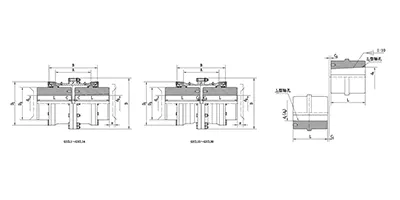
GICL Crown Gear Coupling
Wide type
GICL drum gear coupling has larger inner teeth width, which can transfer torque while compensating for larger axial displacement. -
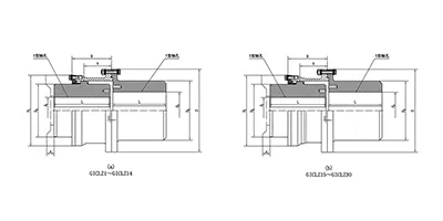
GICLZ Crown Gear Coupling
with intermediate shaft
Half of the GICLZ drum gear coupling adopts a non-toothed semi-coupling sleeve structure, which is usually connected in pairs or used in occasions with small angular displacement. -
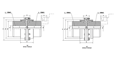
GIICL Crown Gear Coupling
Narrow type
GIICL drum gear coupling has small inner teeth width, which can transfer torque while compensating for small axial displacement. Also, its structure is compact and the moment of inertia is low. -
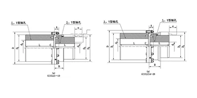
GIICLZ Crown Gear Coupling
with intermediate shaft
Half of the GIICLZ drum gear coupling adopts a non-toothed semi-coupling sleeve structure, which is usually connected in pairs or used in occasions with small angular displacement. Also, its structure is compact and the moment of inertia is low. -
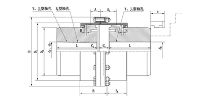
GCLD Crown Gear Coupling
for motor shaft extension
GCLD drum gear coupling is generally used for direct connection with the motor, so it generally has a higher speed and compact structure. -
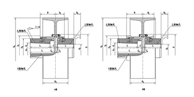
NGCL Crown Gear Coupling
with brake wheel
NGCL drum gear coupling is designed with a brake wheel, suitable for situations where braking is required. -
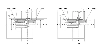
NGCLZ Crown Gear Coupling
with brake wheel
NGCLZ drum gear coupling is designed with a brake wheel, suitable for situations where braking is required. Half of its structure adopts a semi-coupling sleeve design, with smaller angular displacement compensation but more stable braking. -
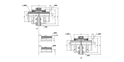
WG Crown Gear Coupling
General purpose
The overall characteristics of WG drum gear coupling are similar to those of other drum gear couplings, but with a larger modulus design, which can generally transmit greater torque. -
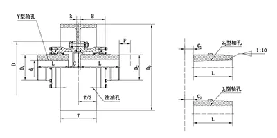
WGZ Crown Gear Coupling
with brake wheel
WGZ drum gear coupling is designed with a brake wheel, suitable for shoe type braking. -
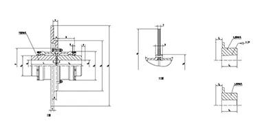
WGP Crown Gear Coupling
with brake disc
WGP drum gear coupling is designed with a brake disc, suitable for disc type braking. -
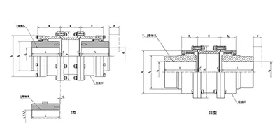
WGT Crown Gear Coupling
with intermediate sleeve
WGT drum gear coupling is designed with indirect tube, suitable for long distance torque transfer. -
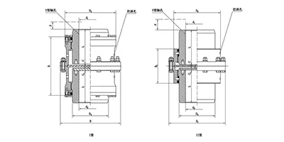
WGC Crown Gear Coupling
for vertical mounting
WGC drum gear coupling is specially designed for situations where vertical transmission is required, suitable for some vertical transmission systems. -
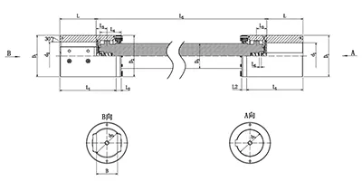
WGJ Crown Gear Coupling
with intermediate shaft
WGJ drum gear coupling is designed with intermediate shaft, suitable for long distance torque transmission, and some are equipped with axial buffers. -
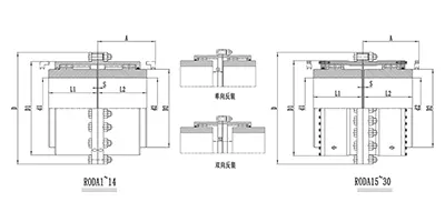
RODA Curved Tooth Coupling
Basic type
RODA series couplings are the basic version of ROD series couplings. They are suitable for most transmission distances and working conditions that do not require an increased movement misalignment compensation. -
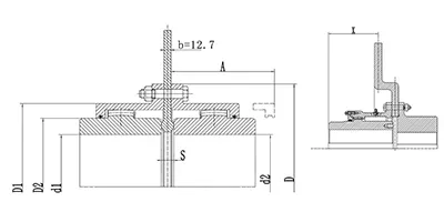
RODP Curved Tooth Coupling
with brake disc
RODP series crowned gear couplings adopt a brake disc design, suitable for working conditions requiring disc braking. -
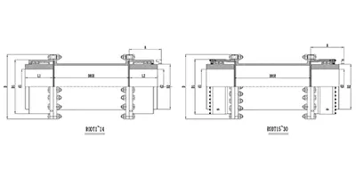
RODT Curved Tooth Coupling
with spacer sleeve
RODT series crowned gear couplings are the extended spacer type of the ROD series, suitable for working conditions requiring a larger transmission distance. -
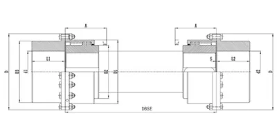
RODX Curved Tooth Coupling
with intermediate shaft
RODX series crowned gear couplings are the extended spacer shaft type of the ROD series. They feature a floating intermediate shaft design and are suitable for working conditions requiring a larger transmission distance. -
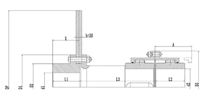
RODF Curved Tooth Coupling
with split brake disc
RODF series crowned gear couplings are the ROD series type with split brake disc. They are suitable for transmission conditions that require matching with disc brakes and allow variable brake positions. -
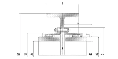
RODW Curved Tooth Coupling
with brake hub
RODW series crowned gear couplings are the ROD series type with brake hub. They are suitable for transmission applications requiring matching with drum brakes for braking functions. -
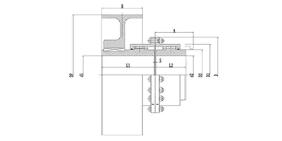
RODU Curved Tooth Coupling
with brake hub
RODU series crowned gear couplings are another brake hub type of the ROD series. They are suitable for transmission applications requiring matching with drum brakes, where braking is applied to one end shaft, and can achieve smoother and more reliable braking performance. -
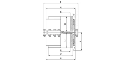
RODV Curved Tooth Coupling
vertical mounting type
RODV series crowned gear couplings are the vertical mounting type of the ROD series. They are suitable for transmission applications requiring vertical torque transmission. -
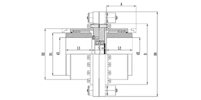
RODM Curved Tooth Coupling
torque limiting type
RODM series crowned gear couplings are the torque-adjustable type of the ROD series. By adjusting the relevant components, the maximum transmission torque can be conveniently set within a certain range. They are suitable for shaft transmission applications requiring safe torque operation to protect critical machine components from overload damage.
Crowned gear couplings belong to the family of flexible mechanical couplings designed to transmit rotational torque between two rotating shafts while accommodating controlled misalignment. Distinct from rigid coupling solutions, they rely on meshed gear profiles to deliver power continuously under offset, angular, and axial displacement conditions. This coupling type is widely recognised for high torque density and compact layout, making it a preferred power transmission component for heavy-duty rotating equipment. The core design philosophy balances robust load carrying capacity with built-in flexibility to reduce stress transfer between connected driving and driven machinery.
Classification and Common Types
Crowned gear couplings can be grouped according to structural arrangement and gear configuration. One major division separates single-flex and double-flex versions. Single-flex crowned gear couplings contain only one set of meshing gear pairs and are limited in the magnitude of allowable misalignment. Double-flex designs incorporate two sets of gear meshes, which greatly expand the permissible range of angular, parallel and axial misalignment.
In terms of profile style, classifications cover straight-tooth gear variants and crowned-tooth gear variants. The crowned modification refers to the curved tooth profile machined on external gear sleeves, which is the defining feature of this coupling category. Common configurations include the basic hub-sleeve assembly, spacer-type units for applications requiring extended shaft separation, and floating-shaft styles for long span transmission layouts. Compact short-coupled types are available for installations with tight axial space constraints.
Structural Composition and Materials
A typical crowned gear coupling assembly consists of several fundamental components. External gear hubs with crowned tooth profiles are mounted onto the driving and driven shafts. Internal gear sleeves mesh with these external gears to form the load-carrying interface. Sealing elements are fitted at the ends of sleeves to retain lubricant and block the ingress of dust, moisture and abrasive contaminants. Fasteners are used to join sleeve segments where applicable, and retaining hardware secures hubs against unintended axial movement.
Material selection targets strength, wear resistance and fatigue performance under cyclic loading. Alloy steel is the dominant material for gear hubs and sleeves, and working tooth surfaces are usually processed to enhance hardness and wear resistance. Sealing components use elastic polymer materials compatible with selected lubricants and operating temperature ranges. Some auxiliary parts adopt carbon steel for structural support where high contact stress is not present. Material matching is arranged to minimise galling and abrasion at the meshing tooth surfaces during repeated relative sliding.
Working Principle
Torque transmission occurs through the engagement between crowned external gear teeth and straight internal gear teeth. When the two connected shafts are perfectly aligned, contact between tooth surfaces is distributed evenly across the tooth width, and rotation is transferred with minimal sliding motion. When misalignment exists between shafts, the curved crowned profile permits the external gear to pivot slightly inside the internal gear sleeve. This controlled pivoting creates limited sliding along the tooth contact surfaces as the coupling rotates.
The crowned tooth geometry prevents concentrated edge loading that would occur with standard straight gear teeth under angular offset. As the coupling revolves, contact zones shift gently across the curved tooth face to distribute contact pressure. Misalignment is absorbed by this small-scale relative movement at the gear mesh rather than imposing bending loads onto the connected shafts, bearings and equipment housings. Lubricant trapped within the mesh cavity forms a protective film over sliding surfaces during operation.
Features and Advantages
The primary advantage of crowned gear couplings is their high torque capacity within a relatively small outer diameter. Compared with many elastomeric flexible couplings, they can transmit substantially higher torque at equivalent envelope dimensions. They support simultaneous angular, parallel and axial misalignment, with double-flex configurations offering much greater compensation capability.
These couplings maintain consistent torsional stiffness under normal operating conditions, which suits systems requiring stable rotational phase relationship between driving and driven sides. They tolerate high rotational speeds when properly balanced and lubricated. Wear rates can be kept low with appropriate lubrication management, leading to long service life in steady operating conditions. The design has good resistance to shock and peak overloads within defined limits.
Potential drawbacks include the requirement for continuous lubrication at gear meshes. They generate more backlash than some low-backlash coupling forms, and they do not provide vibration damping through material elasticity, unlike elastomeric coupling alternatives. Sealing integrity is critical to prevent lubricant loss and abrasive contamination.
Applicable Conditions and Industry Sectors
Crowned gear couplings perform best under steady or periodically fluctuating torque loads where moderate to significant shaft misalignment is anticipated. They are suitable for continuous rotation at medium and high speeds, and can operate across a broad temperature range bounded only by lubricant and seal performance. They are less ideal for applications demanding zero backlash or high levels of vibration isolation.
Major application areas cover heavy processing and rotating machinery sectors. They are widely deployed on fans, blowers and large pumps in fluid handling systems. Conveying and bulk material processing equipment uses them to connect drive motors and reduction gearboxes. They appear in mill drives, mixers and agitators for material processing lines. Compressor systems, generator drives and industrial test stands also adopt this coupling type for high-power transmission needs. Marine auxiliary machinery and mining transfer equipment are other common application scenarios.
Installation and Commissioning Guidelines
Prior to installation, all component surfaces are inspected for burrs, scratches and foreign debris. Gear meshing zones and sealing grooves are cleaned thoroughly. Hubs are fitted onto shaft ends following proper fit practice; interference or transition fits are commonly used to prevent hub rotation relative to the shaft. Care is taken to avoid hammering directly on gear teeth during mounting to prevent tooth damage.
After hub positioning, sleeve assemblies are installed and sealing elements are checked for correct seating. Initial alignment is performed carefully to minimise operating misalignment, even though the coupling can accommodate offset. Excessive misalignment beyond the designed allowance accelerates tooth wear and heat generation. Once mechanical assembly is finished, lubricant is introduced into the internal cavity of the sleeve to fill the mesh region.
Commissioning starts with a no-load trial run. Operators monitor for abnormal noise, temperature rise or lubricant leakage at seal points. If irregular heating or knocking sounds appear, the unit should be shut down to recheck alignment, lubricant fill level and seal installation. Load is applied gradually after the no-load phase confirms stable operation.
Selection and Customisation
Core selection parameters include rated operating torque, peak torque from transient load events, maximum continuous rotational speed, shaft diameters on both driving and driven sides, and the required distance between shaft ends. The expected magnitude of misalignment is evaluated to decide between single-flex and double-flex structures. Space constraints determine whether standard, spacer or floating-shaft designs are appropriate.
Lubrication environment, ambient temperature and exposure to dust or corrosive agents influence seal design and material choices. Custom adjustments can be made for special shaft hole configurations, non-standard spacer lengths, modified sealing arrangements and surface treatment specifications. When selecting, safety margins are incorporated against anticipated overloads. It is important to match the coupling’s speed rating to the maximum operating speed of the system to avoid balance-related issues. Customised versions are engineered to satisfy unique layout or environmental requirements without altering the fundamental crowned gear working principle.
Operation and Maintenance
Routine maintenance centres mainly on lubrication management. The lubricant type, fill quantity and replenishment interval follow the requirements for the specific operating conditions. Degraded or contaminated lubricant must be drained and replaced on schedule, as contaminated lubrication causes rapid abrasive wear of gear teeth. Seals are inspected regularly for leakage, cracking or hardening; worn seals are replaced promptly to keep contaminants out and lubricant contained.
Periodic external checks during operation include running temperature, noise signature and visible lubricant leaks. Disassembly inspection is carried out at planned intervals to examine gear tooth contact surfaces for pitting, scoring or wear patterns. If uneven wear is discovered, shaft alignment should be re-evaluated. Gear tooth surfaces showing heavy wear or fatigue damage require component replacement before failure occurs.
When equipment is idle for extended periods, occasional shaft rotation helps prevent lubricant settling and localised corrosion on meshing tooth faces. Maintenance records track lubrication cycles, seal replacements and gear condition observations to predict remaining service life and schedule downtime for service. Proper maintenance practices extend service life and reduce unplanned shutdowns caused by coupling failure.