In the complex mechanical transmission systems of modern industrial production, coupling components undertake the critical task of connecting two rotating shafts to transmit torque and rotational motion. Among numerous coupling types, crown gear coupling stands out as a reliable rigid-flexible transmission component with unique tooth profile design and compact mechanical structure. It has become an indispensable core part in heavy-duty mechanical equipment due to its excellent torque transmission capacity, outstanding misalignment compensation performance and stable operational reliability. Different from ordinary straight gear couplings and elastic couplings, the crown gear coupling adopts a special crowned outer gear structure, which effectively optimizes the stress distribution of meshing teeth while retaining the advantages of high rigidity and high transmission efficiency of gear couplings. This mechanical part can adapt to harsh working conditions such as heavy load, frequent start-stop and complex shaft position deviation, achieving balanced coordination between structural stability and motion flexibility. With the continuous upgrading of industrial manufacturing technology, crown gear coupling has been continuously optimized in structural design and material configuration, and its application scope has gradually expanded from traditional heavy industry to light industry, energy and transportation fields, providing stable guarantee for the long-term efficient operation of various mechanical transmission systems.

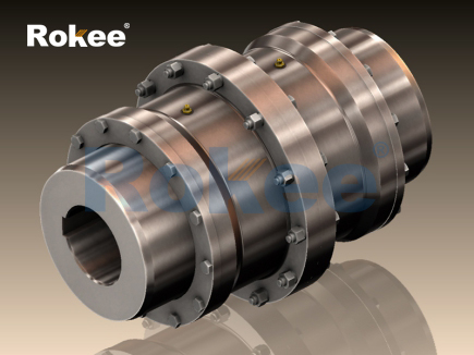
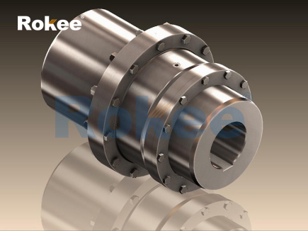
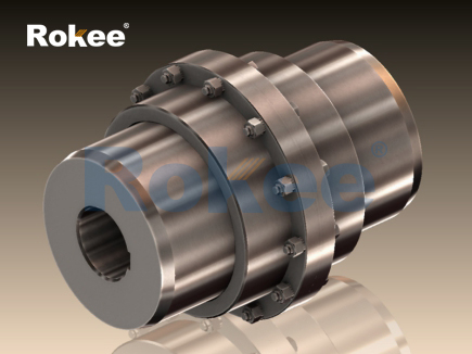
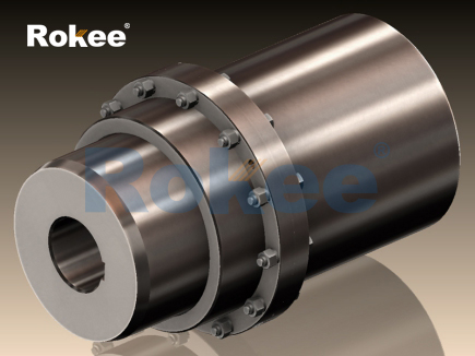
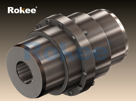
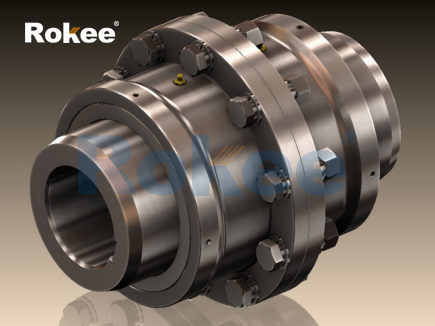
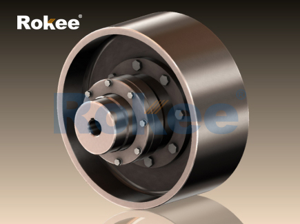
The basic structure of crown gear coupling follows a simple and rigorous combined assembly mode, mainly composed of two flanged half couplings with outer crowned teeth, an inner gear ring and a set of sealing and lubrication auxiliary components. The outer gear of the half coupling is processed into a spherical crown shape through precision machining technology, and the curved tooth surface can produce flexible contact with the straight tooth surface of the inner gear ring during meshing. This special tooth surface structure is the core difference between crown gear coupling and conventional straight gear coupling. The inner gear ring adopts an integral annular structure with uniformly distributed straight internal teeth on the inner wall, which is matched with the outer crowned teeth to form a meshing transmission pair. In terms of connection mode, the two half couplings are respectively fixed on the driving shaft and the driven shaft, and the inner gear ring is sleeved on the outer sides of the two groups of meshing teeth to realize the synchronous rotation of the two shafts. In order to ensure the internal lubrication environment and prevent external impurities from invading the meshing area, sealing components such as rubber sealing rings and protective end covers are installed at the joints of the inner gear ring and the half couplings. These sealing parts can effectively isolate dust, moisture and abrasive particles in the external working environment, avoid tooth surface abrasion and corrosion, and maintain the stability of internal lubricating grease. In addition, the overall structure adopts a split assembly design, which does not need to displace the main equipment on both sides during installation and disassembly. The simple assembly process greatly reduces the difficulty of later maintenance and brings convenience for daily equipment inspection and component replacement.
The unique structural design endows crown gear coupling with superior comprehensive performance, which is prominently reflected in load bearing capacity, transmission efficiency, misalignment compensation and operational stability. In terms of torque transmission, the curved contact mode of crowned teeth increases the contact area between meshing teeth, disperses the local stress generated during torque transmission, and enables the coupling to bear large instantaneous impact load and continuous heavy load. Compared with gear couplings of the same specification and size, its torque bearing capacity is significantly improved, and it can maintain stable transmission state under long-term heavy-duty working conditions. The transmission efficiency of crown gear coupling remains at an excellent level, with extremely low power loss during operation. The smooth curved tooth surface reduces meshing friction resistance, and the matching internal lubrication environment further lowers friction loss, realizing efficient energy transmission. In terms of axis deviation compensation, the spherical crown tooth structure can adapt to radial deviation, angular deviation and axial displacement generated by installation errors and equipment operation vibration. The flexible meshing state avoids additional mechanical stress on the shaft, bearing and other components caused by shaft misalignment, and effectively reduces equipment vibration and operation noise. Moreover, the main components of the coupling are made of high-strength alloy materials through forging and heat treatment processes, which have good wear resistance, fatigue resistance and structural rigidity. Even in harsh working environments such as high dust, high humidity and variable temperature, it can maintain stable mechanical performance without obvious structural deformation and performance attenuation. The reasonable sealing structure also prolongs the service life of internal gear teeth, reduces the frequency of lubricating grease replacement, and lowers the overall operation and maintenance cost of mechanical equipment.
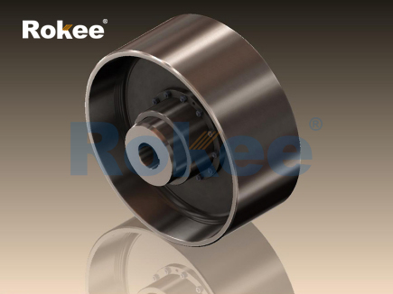
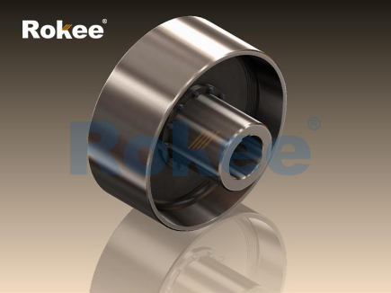
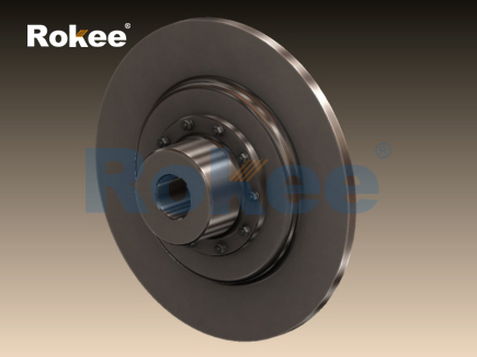
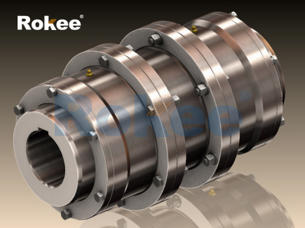
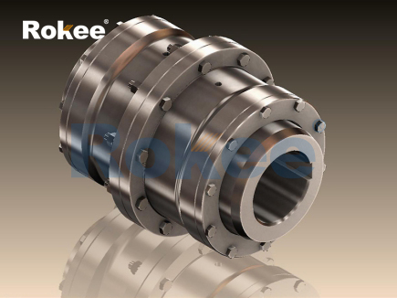
According to structural differences, functional characteristics and application scenarios, crown gear couplings can be divided into multiple classification types, and each type has targeted structural optimization and performance adjustment to adapt to differentiated industrial working conditions. The most common classification is based on structural combination forms, including basic type crown gear coupling, intermediate shaft type crown gear coupling and brake wheel type crown gear coupling. The basic type has the simplest structural composition, without additional auxiliary components, and is mainly used for short-distance shaft connection with small deviation and stable load. It features compact overall size and low manufacturing cost, suitable for conventional medium and small power transmission equipment. The intermediate shaft type is added with an intermediate connecting shaft on the basis of the basic structure, which realizes long-distance transmission between two shafts. This type of coupling optimizes the vibration resistance structure of the intermediate shaft, can reduce the resonance phenomenon during long-distance transmission, and is widely used in long-axis transmission systems such as belt conveyors and large fans. The brake wheel type integrates the brake wheel structure on the outer side of the half coupling, which can be directly matched with external brake components without additional braking devices. The integrated structure saves installation space, and can adapt to working conditions requiring frequent start-stop and forward-reverse rotation, such as cranes and rolling mills.
In addition to the above structural classification, crown gear couplings can also be classified according to sealing forms and processing precision. In terms of sealing structure, they are divided into fully sealed type and semi-sealed type. The fully sealed type adopts multi-layer sealing protection, which can completely isolate external pollutants, and is suitable for severe working environments such as mining and metallurgy with heavy dust and corrosive substances. The semi-sealed type has a relatively simple sealing structure, which is light in weight and low in cost, and is mostly used for indoor mechanical equipment with clean working environment and low corrosion risk. According to machining precision, it can be divided into ordinary precision type and high-precision type. The ordinary precision type is suitable for general industrial transmission equipment with low requirements for rotation accuracy, while the high-precision type adopts fine grinding process for tooth surface processing, with extremely low rotation runout error, which can meet the high-precision transmission requirements of energy equipment and precision processing machinery. Different types of crown gear couplings follow the basic meshing principle of crowned teeth, and adjust structural parameters such as tooth width, outer diameter and wall thickness to match different load levels and installation space requirements, forming a complete product system covering light load to heavy load, short distance to long distance, and conventional environment to harsh environment.
With its diverse structural types and excellent comprehensive performance, crown gear couplings have been widely applied in multiple industrial fields, becoming an important basic component to ensure the stable operation of mechanical equipment. In the metallurgical industry, this coupling is applied to rolling mills, smelting auxiliary machinery and metal processing transmission equipment. The equipment in this industry often bears strong impact load and high-temperature environmental interference, and the high load-bearing capacity and high-temperature resistance of crown gear couplings can adapt to such harsh working conditions, maintaining continuous and stable torque transmission during metal rolling and smelting processing. In the mining industry, it is installed on crushers, ball mills and mining conveying machinery. The complex working conditions such as dust pollution and vibration shock in mining sites put forward high requirements for the wear resistance and sealing performance of couplings, and the fully sealed crown gear coupling can effectively prevent dust from entering the meshing area, reducing tooth surface wear and failure probability.
In the heavy machinery industry, crown gear couplings are commonly used in lifting equipment such as cranes and hoists. These devices need to realize frequent start-stop and forward-reverse rotation, and the good deviation compensation and impact resistance of the coupling can buffer the instantaneous torque change generated during equipment switching, avoiding mechanical fatigue damage of the shaft system. In the building materials and chemical industry, it is matched with rotary kilns, large water pumps and stirring machinery. Such equipment has long operation cycle and stable load, and the low maintenance characteristics of crown gear couplings can reduce the downtime caused by component maintenance, improving the continuous operation efficiency of the production line. In addition, in the field of new energy and transportation, high-precision crown gear couplings are applied to power generation transmission equipment and port handling machinery. The high transmission efficiency and low vibration characteristics can reduce energy loss, realizing energy-saving and efficient operation of equipment.
In the actual industrial application process, the reasonable selection and standardized installation of crown gear couplings are crucial to give full play to their structural performance advantages. Mechanical designers need to comprehensively consider key factors such as equipment transmission power, operating speed, load characteristics and installation space, and select appropriate coupling types and structural specifications. During the installation process, it is necessary to control the coaxiality error of the two connecting shafts within a reasonable range to avoid excessive initial deviation causing additional abrasion of meshing teeth. Daily maintenance work should focus on checking the sealing performance and internal lubrication state, regularly replacing lubricating grease suitable for the working temperature, and cleaning the external dust and attachments of the coupling. For the coupling working in high-frequency vibration and heavy load environment, regular inspection of tooth surface wear and bolt fastening state is required to eliminate potential mechanical failures in advance.
Looking at the development trend of mechanical transmission components, crown gear coupling still has broad optimization space and application potential. With the continuous progress of material science and precision machining technology, higher-strength and more corrosion-resistant alloy materials will be applied to the production of couplings, further improving the structural durability and environmental adaptability of products. The intelligent optimization of structural design will reduce the overall weight while ensuring load-bearing performance, realizing lightweight and compact structural iteration. In the future industrial system, crown gear coupling will further expand its application scope in emerging fields such as intelligent manufacturing and new energy equipment, and continuously optimize the transmission stability and service life through technological innovation. As a mature and reliable transmission component, crown gear coupling will always occupy an important position in the field of mechanical transmission, providing solid technical support for the stable operation and efficient production of various industrial mechanical equipment.
pu sandwich panel line,pu sandwich panel machine,sandwich panel machine
« Crown Gear Couplings » Latest Update Date: May 9, 2026
https://www.rokeecoupling.net/tags/crown-gear-couplings.html