Universal Joint Drive Shafts

Heavy-duty Universal Joint Drive Shafts with precision U-joints. Wear-resistant, low vibration, fits truck, PTO & industrial equipment. Replacement & custom drive shafts available. Rokee is a universal joint drive shafts supplier in China. We support custom orders and offer direct factory sales, providing reliable products with flexible solutions for global clients.
Universal joint drive shafts are flexible transmission assemblies that transfer rotational torque while compensating for angular, axial and minor radial misalignment between non-collinear shafts. They mainly include cross-pin, ball-cage and telescopic types, built with yokes, cross spindles, splines, bearings and seals from high-strength steel and wear-resistant materials. By offsetting speed fluctuation with paired universal joints, they achieve stable power transmission. Widely used in machinery, mining and agriculture, they require proper installation, reasonable selection and regular lubrication and inspection for reliable service.
-
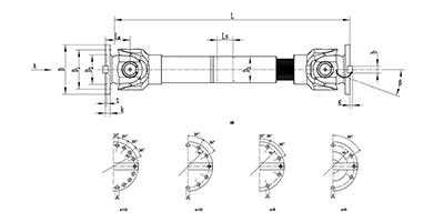
SWC-BH Cardan Shaft
Standard telescopic welded
SWC-BH universal shaft coupling with integral fork head, welded pipe structure and spline telescopic function. It compensates angular deflection and axial displacement for torque transmission, widely used in metallurgy, rolling mills and heavy machinery. -
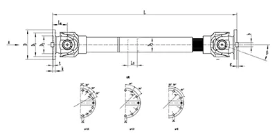
SWC-CH Cardan Shaft
long telescopic welded
SWC-CH long telescopic welded cross-shaft universal coupling adopts integral yoke structure, delivering reliable power transmission with both angular and long-range axial compensation. -
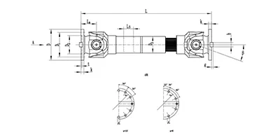
SWC-DH Cardan Shaft
Short Telescopic Welded
SWC-DH cross shaft universal coupling adopts integral yoke & welded pipe structure, featuring short telescopic spline for small axial displacement compensation. It allows large working angle, transmits torque steadily and efficiently, ideal for heavy industrial drives where shaft misalignment exists. -
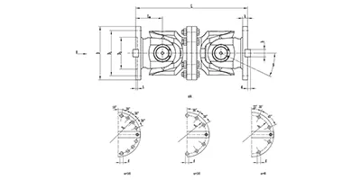
SWC-WD Cardan Shaft
Non-telescopic Short
SWC-WD cross shaft universal coupling is a non-telescopic short structure cardan coupling. It can only compensate angular displacement, features compact size, stable torque transfer and large allowable working angle, suitable for heavy-duty transmission systems with no axial movement requirement. -
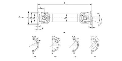
SWC-WH Cardan Shaft
Non-telescopic Welded
SWC-WH cross shaft universal joint coupling adopts welded pipe structure with no telescopic spline. It only compensates angular displacement, delivers stable torque transmission and allows large working angle. Suitable for heavy-duty drive systems where axial displacement is not needed. -
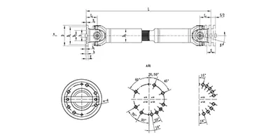
SWP-A Cardan Shaft
Long Telescopic
SWP-A type is a long telescopic cross shaft universal joint coupling (cardan shaft) with spline telescopic structure. It transmits torque between non-coaxial shafts, compensates angular deflection and axial length variation, widely used in metallurgy, lifting and other heavy machinery. -
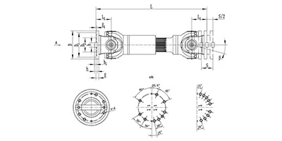
SWP-B Cardan Shaft
short telescopic
SWP-B type is a short telescopic cross shaft universal coupling (cardan shaft). Equipped with spline telescopic joint, it transfers torque between offset shafts, accommodates angular deflection and axial movement, widely used in metallurgy, mining and heavy equipment. -
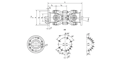
SWP-C Cardan Shaft
Non-telescopic Short
SWP-C type is a short non-telescopic cross shaft universal joint coupling (cardan drive shaft). It transmits torque between non-coaxial shafts and accommodates angular deflection only, suitable for heavy machinery with fixed axial installation distance. -
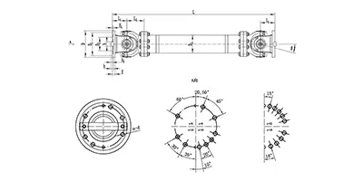
SWP-D Cardan Shaft
non-telescopic long
SWP-D non-telescopic long cross universal joint coupling adopts split bearing housing structure, transmits large torque with angular compensation, fixed overall length without axial expansion, widely applied for rolling mills and heavy transmission systems.
Universal joint drive shafts are mechanical power transmission assemblies designed to transfer rotational torque between two shafts whose axes are not collinear. They accommodate angular misalignment, axial displacement and minor radial offset during operation, serving as a flexible connection between driving and driven components. As a core transmission component, they bridge power sources and executing parts in rotating machinery, compensating for position changes caused by assembly tolerance, component deformation, vibration and movement during equipment running. Unlike rigid shaft connections, universal joint drive shafts maintain stable torque output even when the relative angle between connected shafts changes continuously.
Classification and Common Types
Universal joint drive shafts can be grouped according to the structural form of the universal joint unit. Single universal joint drive shafts contain one universal joint and are suitable for scenarios with small fixed angular offset. Double universal joint drive shafts adopt two universal joints matched with an intermediate shaft, which can effectively eliminate speed fluctuation and is the most widely adopted type. Telescopic universal joint drive shafts add a sliding spline structure on the intermediate shaft section to adapt to variable axial distance between connected equipment. Constant velocity universal joint drive shafts deliver uniform angular velocity output at large deflection angles, avoiding periodic speed variation.
Common structural variants include cross-pin universal joint drive shafts, ball-cage universal joint drive shafts and ball-trunnion universal joint drive shafts. Cross-pin types feature simple construction and strong load capacity for heavy-duty transmission. Ball-cage types support larger deflection angles and smooth rotation for medium and high-speed conditions. Ball-trunnion types balance compact size and vibration resistance for limited installation space.
Structural Composition and Materials
A typical universal joint drive shaft consists of universal joint assemblies, an intermediate shaft tube, spline pairs, bearing assemblies, sealing components and connecting flanges or yokes. The universal joint assembly includes yokes, cross spindles, rolling bearings and retaining parts. The spline pair is formed by matching internal and external splines to realize telescopic movement. Seals prevent dust, moisture and abrasive particles from entering bearing spaces and retain internal lubricant. Connecting yokes and flanges provide mounting interfaces for external equipment.
High-strength alloy steel is the primary material for cross spindles, yokes and spline shafts, offering good toughness and fatigue resistance under alternating torque loads. Shaft tubes often use seamless steel tubes to balance torsional rigidity and lightweight performance. Bearing rolling elements use bearing steel with high hardness and wear resistance. Sealing parts adopt elastomer materials with stable performance under variable temperature and friction conditions. Surface treatment processes are applied to key components to enhance corrosion resistance and reduce wear.
Working Principle
Torque is transmitted from the driving shaft to the driving yoke of the universal joint. The cross spindle acts as a hinge, transferring rotation to the driven yoke while allowing the two yokes to form an included angle. For a single universal joint, the instantaneous angular velocity of the driven shaft fluctuates periodically when a deflection angle exists. When two universal joints are arranged in series with proper phase alignment, the speed fluctuation generated by the first joint can be offset by the second joint, achieving approximately constant angular velocity transmission at the driven end.
For telescopic configurations, the spline pair slides relatively along the axial direction as the spacing between the driving and driven ends changes, without interrupting torque transfer. Constant velocity structural designs adopt special rolling element arrangements to synchronize the angular velocity of input and output shafts at large deflection angles, removing the inherent speed fluctuation of ordinary cross-type universal joints.
Characteristics and Advantages
The most prominent feature of universal joint drive shafts is the capability to compensate for multi-directional misalignment. They can work stably with angular, axial and minor radial offset simultaneously. Compared with other flexible transmission schemes, they deliver high torque transmission efficiency and small power loss during rotation. The assemblies can withstand heavy alternating loads and have strong impact resistance under sudden load changes.
The modular structure supports convenient disassembly and part replacement. The transmission stiffness is controllable, and torsional vibration can be suppressed through reasonable structural matching. Suitable for a wide rotational speed range, they can operate under both low-speed heavy-load and medium-speed transmission conditions. The layout flexibility allows arrangement in narrow and irregular installation spaces where rigid shafts cannot be deployed.
Applicable Working Conditions and Application Industries
Universal joint drive shafts adapt to working environments with variable relative positions between driving and driven parts. They can operate under cyclic load, intermittent operation and continuous rotation conditions. Proper sealing configurations enable application in dusty, humid and moderately polluted environments. Operation parameters are limited by the maximum allowable deflection angle, rated torque and linear speed; excessive deflection or overload will shorten service life and amplify vibration.
They are widely used in engineering machinery, transportation equipment, agricultural machinery, metallurgical equipment, mining machinery, packaging and printing equipment, and general industrial transmission systems. In mobile machinery, they transmit power between engines, gearboxes and walking or executing components that move relative to each other. In fixed industrial equipment, they connect separate power units and actuators where installation misalignment or thermal deformation exists.
Installation and Commissioning Points
Before installation, check all components for deformation, crack, wear and seal damage, and confirm that the matching surfaces are clean. Align the phase position of double universal joints correctly to avoid abnormal speed fluctuation and vibration. Control the deflection angle of each universal joint within the allowable range; distributing the total misalignment evenly on two joints can achieve better running performance.
Match the spline insertion depth reasonably to reserve enough telescopic stroke while avoiding over-insertion or separation during operation. Fasten connecting fasteners following specified tightening requirements to prevent loose connections under alternating torque. After preliminary assembly, manually rotate the whole shaft assembly to verify smooth rotation without jamming or abnormal friction.
In commissioning, run the equipment at low speed first and observe vibration, noise and temperature change of the universal joint parts. Adjust the installation position if obvious vibration or impact occurs. Check the sealing state after trial operation to confirm no lubricant leakage. Gradually increase the load and running speed to the normal working state after stable low-speed operation.
Selection and Customization
Selection starts with confirming the required rated torque, working rotational speed, maximum deflection angle and required axial telescopic stroke. It is necessary to consider load characteristics, including continuous load, impact load and alternating load frequency. The installation space size, connection interface form and arrangement layout also determine the overall dimension and structural type.
When standard types cannot meet requirements, customized design can be carried out. Customizable items include the length of the intermediate shaft, spline specification, connection flange shape, sealing structure and special surface treatment. For special working environments, material matching and protective structures can be adjusted. The design process needs to balance strength, rotation balance, weight and installation boundary to avoid resonance in the normal working speed range.
Operation and Maintenance
Regular lubrication is the core maintenance item. Lubricant should be replenished at specified intervals for universal joint bearings and spline pairs. Use suitable lubricant types matching the working temperature and load condition. Inspect seals periodically and replace damaged seals timely to prevent lubricant loss and pollutant ingress.
Routine inspection covers abnormal noise, vibration and temperature rise during operation. Check fastener tightness and connection state regularly. Examine the wear degree of cross spindles, bearing rollers and spline surfaces. If excessive clearance, pitting or abrasion is found on key friction pairs, replace the relevant components promptly.
Avoid long-term overload operation and operation beyond the maximum allowable deflection angle. When the equipment is idle for a long time, rotate the drive shaft periodically to prevent local corrosion and lubricant failure. After impact incidents or equipment collision, conduct a full inspection of the universal joint drive shaft for hidden structural damage before restarting operation.