As an indispensable mechanical transmission component in modern mechanical systems, the universal shaft serves as a critical connecting medium for power transmission between spatially offset rotating shafts. It effectively solves the transmission limitations of rigid connecting structures, enabling stable torque transmission even when there are angular deviations, axial displacements and radial misalignments between connected shafts. With the continuous advancement of mechanical manufacturing technology and the diversification of industrial application scenarios, universal shafts have evolved into multiple structural types with distinct performance characteristics, adapting to complex working conditions such as variable load, alternating rotation angle and harsh operating environments. The rational design of internal structures and the optimization of material properties endow universal shafts with reliable mechanical stability, fatigue resistance and vibration absorption capacity, making them widely applied in transportation machinery, industrial processing equipment, agricultural machinery and engineering construction facilities. Exploring the structural composition, core performance indicators, classification characteristics and practical application values of universal shafts can provide clear theoretical references for mechanical selection, structural optimization and equipment maintenance in industrial production.
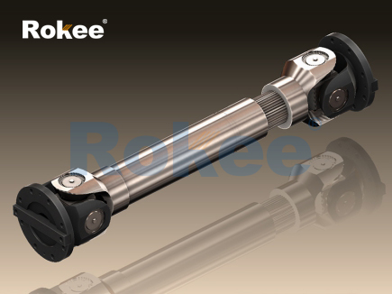
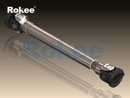
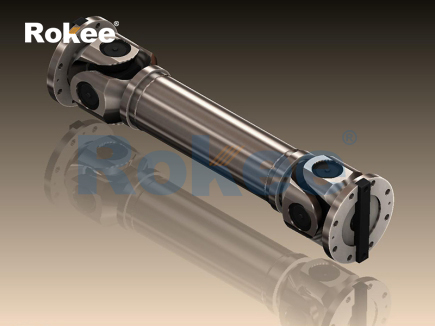
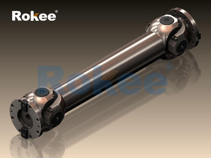
The basic structural composition of a universal shaft follows a mature mechanical transmission logic, and each component undertakes differentiated functional responsibilities to jointly realize flexible power transmission. The core components generally include joint forks, intermediate transmission shafts, hinged connecting parts and auxiliary sealing and damping structures. The joint forks are located at both ends of the universal shaft, with standardized connecting structures that can be stably assembled with driving and driven shafts, ensuring the synchronization of rotational motion. The intermediate transmission shaft is the main load-bearing part, which bears torsional torque and bending stress during operation; its wall thickness, cross-sectional shape and overall length are designed according to load requirements to balance structural rigidity and lightweight performance. Hinged connecting parts are the key functional components of the universal shaft, which enable angular deflection between adjacent structures. These movable connecting parts adopt precision-fit mechanical structures to reduce friction resistance during relative rotation and ensure flexible angle adjustment. Auxiliary structures such as sealing sleeves and buffer gaskets are installed at the movable joints, which can block external dust, moisture and corrosive substances, reduce mechanical wear caused by dry friction, and extend the continuous service life of the universal shaft. The internal assembly clearance of all components is strictly controlled within a reasonable range to avoid transmission jitter and torque loss caused by excessive clearance, while reserving a tiny deformation space to cope with slight mechanical displacement generated during equipment operation.
The comprehensive performance of a universal shaft determines its applicable working conditions and service cycle, and the core performance indicators cover mechanical bearing capacity, motion transmission stability, environmental adaptability and structural durability. In terms of mechanical bearing performance, the universal shaft needs to withstand continuous torsional torque and instantaneous impact load during operation. High-quality structural designs can maintain stable mechanical properties under long-term variable load conditions without permanent deformation or structural fracture. The maximum deflection angle is a key motion performance parameter, reflecting the flexible adjustment capability of the universal shaft when the connected shafts are misaligned; different structural designs correspond to different safe deflection ranges, which directly affect the flexibility of mechanical layout. Transmission stability is reflected in the uniformity of rotational speed and torque output. Advanced structural optimization can suppress speed fluctuation during rotation, reduce vibration amplitude and lower operating noise, which is particularly important for precision mechanical equipment that requires smooth transmission. Environmental adaptability includes temperature resistance, corrosion resistance and dustproof performance. Universal shafts applied in extreme working environments usually undergo surface treatment to resist oxidation and chemical erosion, ensuring structural integrity in high-temperature, humid and dusty working scenes. Structural durability depends on material toughness and wear resistance; excellent raw materials and processing techniques can reduce fatigue wear caused by repeated mechanical movement, realizing long-term continuous operation and lowering equipment maintenance frequency.
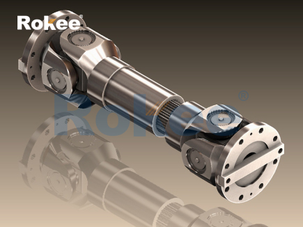
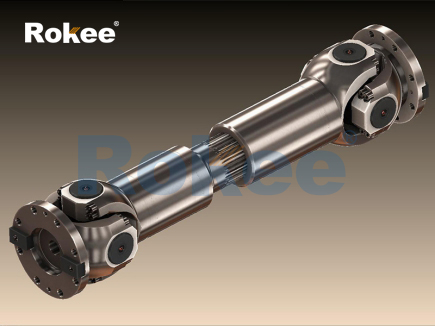
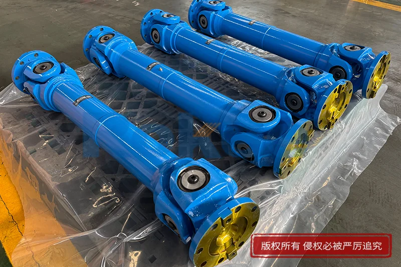
According to structural differences and motion transmission characteristics, universal shafts can be divided into several mainstream types with distinct application orientations, and each type has unique structural advantages and performance boundaries. Single-joint universal shafts are the most basic structural form, composed of a single group of hinged connecting components and two joint forks. This type of universal shaft has a simple structure, small overall size and low assembly difficulty, and is suitable for working scenarios with small shaft spacing and limited deflection angle. Its structural limitation lies in the non-uniform rotation speed during deflection, which will produce slight transmission vibration when the deflection angle increases, so it is mostly used in low-speed and light-load mechanical systems. Double-joint universal shafts are formed by connecting two single-joint structures through an intermediate shaft. The tandem arrangement of double hinged structures can compensate for the speed fluctuation defect of single-joint structures, realizing approximately constant-speed torque transmission. This structure allows a larger shaft deflection angle, and has better adaptability to spatial misalignment of shafts, making it widely used in medium-load and medium-speed transmission scenarios.
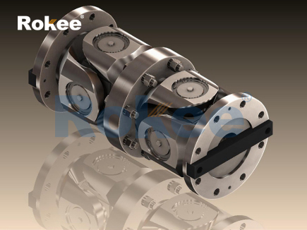
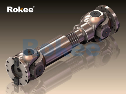
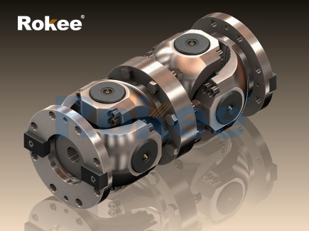
Constant-velocity universal shafts are a high-performance improved type, adopting special curved track structures and rolling friction components to realize strictly synchronous rotation of driving and driven shafts regardless of deflection angles. Different from the hinged rotation mode of traditional universal shafts, the internal rolling parts of constant-velocity universal shafts can evenly disperse contact pressure, effectively reducing friction loss and mechanical vibration. This type of universal shaft has outstanding high-speed transmission stability, small operating noise and high torque transmission efficiency, and is commonly used in high-precision and high-speed mechanical transmission systems. In addition, heavy-duty reinforced universal shafts are specially designed for extreme load working conditions. They are optimized in terms of component thickness, connecting structure and material hardness, with enhanced bending and torsion resistance. The local stress concentration points of the structure are polished and strengthened to avoid fracture failure under heavy impact loads. Although the self-weight and manufacturing cost of heavy-duty universal shafts are higher, their reliable bearing capacity makes them irreplaceable in heavy industrial machinery.
Different types of universal shafts have clear application boundaries, and their practical usage scenarios are closely matched with their structural performance characteristics, covering multiple industrial fields. In the field of transportation machinery, universal shafts are applied to the power transmission systems of mobile transportation equipment. They connect power output components and walking execution components, adapting to the spatial position changes of mechanical parts caused by jolting during driving. The constant-velocity universal shafts with stable high-speed performance are widely used in daily transportation equipment to ensure smooth power output during driving and steering. In industrial production equipment, double-joint universal shafts are mostly adopted in automated processing machinery, conveying equipment and rotating transmission devices. They can tolerate installation errors and slight displacement during equipment operation, maintain continuous and stable power transmission, and reduce the failure rate of mechanical transmission links.
In agricultural machinery, the working environment is usually harsh with a large amount of sediment and humid air, so universal shafts with good sealing performance and corrosion resistance are selected to match farming machinery such as tillage equipment and harvesting machines. These universal shafts need to cope with complex terrain jolts and intermittent impact loads, and their durable structural design can adapt to long-term outdoor operation. Engineering construction machinery puts forward higher load-bearing requirements for universal shafts, and heavy-duty reinforced universal shafts are installed on large mechanical equipment such as excavators, loaders and cranes. They bear huge torsional stress and impact load to complete power transmission in heavy-duty operation. In addition, some miniature precision universal shafts are applied in instrument manufacturing and small automated mechanical devices. These lightweight structures with high transmission accuracy meet the power transmission requirements of compact mechanical structures and realize precise motion control.
In the actual application process, the service effect and service life of universal shafts are affected by multiple external factors, and standardized use and maintenance methods can effectively optimize their operating performance. The installation process needs to ensure the coaxiality of the connecting shaft as much as possible, reduce the long-term deflection angle of the universal shaft, and avoid excessive stress wear of hinged parts caused by long-term large-angle deflection. The operating load should be controlled within the rated bearing range; long-term overload operation will lead to irreversible fatigue deformation of the transmission shaft and shorten the service cycle. Regular cleaning and lubrication of movable joints can reduce friction and wear between internal components, and the replacement of sealing accessories on schedule can prevent external impurities from entering the internal structure to cause abrasion and corrosion. For universal shafts that have been used for a long time, regular inspection of structural deformation and connection tightness is required to eliminate potential safety hazards such as loose assembly and structural fatigue fracture.
With the continuous upgrading of industrial manufacturing technology, the optimization direction of universal shafts is gradually moving towards lightweight structure, high transmission efficiency and strong environmental adaptability. Advanced smelting and processing technologies are used to optimize raw material components, so as to reduce the self-weight of universal shafts while ensuring mechanical strength and improve the energy utilization rate of mechanical transmission. The internal friction structure is further optimized to reduce power loss during torque transmission and improve the overall working efficiency of mechanical equipment. In terms of structural design, modular assembly is adopted to simplify the replacement and maintenance steps of components, lower the later use cost of equipment. Meanwhile, aiming at special working environments such as ultra-low temperature, high humidity and strong corrosion, targeted surface modification treatment technologies are applied to expand the environmental adaptation range of universal shafts. As a basic transmission component, universal shafts will always occupy an important position in the mechanical industry. The continuous improvement of their structural performance and the expansion of application fields will further promote the efficient and stable operation of modern mechanical systems, providing solid technical support for the sustainable development of various industrial sectors.
pu sandwich panel line,pu sandwich panel machine,sandwich panel machine
« Universal Shafts » Latest Update Date: May 9, 2026
https://www.rokeecoupling.net/tags/universal-shafts.html