Universal Joint Cardan Shafts

Buy premium Universal Joint Cardan Shafts direct from manufacturer. Wide range of models, precise machining, competitive price. Custom sizes & OEM available. Rokee is a universal joint cardan shafts supplier in China. We support custom orders and offer direct factory sales, providing reliable products with flexible solutions for global clients.
Universal joint cardan shafts are flexible power transmission parts that transfer rotary torque between misaligned shafts, accommodating angular, axial and minor radial offset. They mainly include single, double, fixed-length and telescopic types. Built with joint heads, cross spiders, bearings, intermediate tubes and spline structures, they rely on the pivoting of cross assemblies to rotate. Widely used in machinery, agriculture and mining, they feature strong misalignment compensation. Proper installation, lubrication and inspection are essential for stable operation and long service life.
-
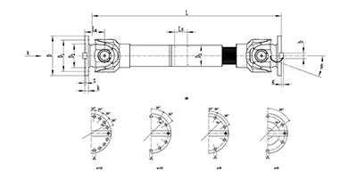
SWC-BH Cardan Shaft
Standard telescopic welded
SWC-BH universal shaft coupling with integral fork head, welded pipe structure and spline telescopic function. It compensates angular deflection and axial displacement for torque transmission, widely used in metallurgy, rolling mills and heavy machinery. -
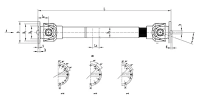
SWC-CH Cardan Shaft
long telescopic welded
SWC-CH long telescopic welded cross-shaft universal coupling adopts integral yoke structure, delivering reliable power transmission with both angular and long-range axial compensation. -
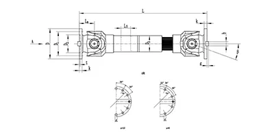
SWC-DH Cardan Shaft
Short Telescopic Welded
SWC-DH cross shaft universal coupling adopts integral yoke & welded pipe structure, featuring short telescopic spline for small axial displacement compensation. It allows large working angle, transmits torque steadily and efficiently, ideal for heavy industrial drives where shaft misalignment exists. -
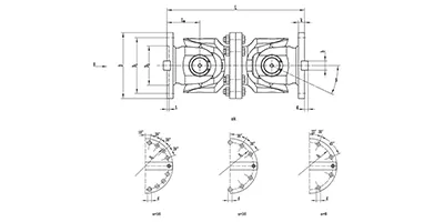
SWC-WD Cardan Shaft
Non-telescopic Short
SWC-WD cross shaft universal coupling is a non-telescopic short structure cardan coupling. It can only compensate angular displacement, features compact size, stable torque transfer and large allowable working angle, suitable for heavy-duty transmission systems with no axial movement requirement. -
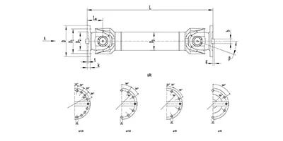
SWC-WH Cardan Shaft
Non-telescopic Welded
SWC-WH cross shaft universal joint coupling adopts welded pipe structure with no telescopic spline. It only compensates angular displacement, delivers stable torque transmission and allows large working angle. Suitable for heavy-duty drive systems where axial displacement is not needed. -
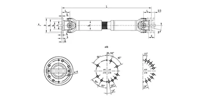
SWP-A Cardan Shaft
Long Telescopic
SWP-A type is a long telescopic cross shaft universal joint coupling (cardan shaft) with spline telescopic structure. It transmits torque between non-coaxial shafts, compensates angular deflection and axial length variation, widely used in metallurgy, lifting and other heavy machinery. -
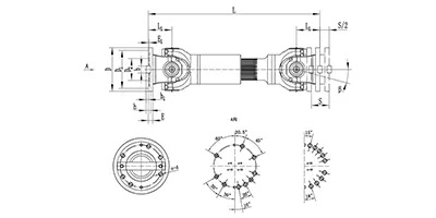
SWP-B Cardan Shaft
short telescopic
SWP-B type is a short telescopic cross shaft universal coupling (cardan shaft). Equipped with spline telescopic joint, it transfers torque between offset shafts, accommodates angular deflection and axial movement, widely used in metallurgy, mining and heavy equipment. -
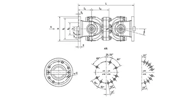
SWP-C Cardan Shaft
Non-telescopic Short
SWP-C type is a short non-telescopic cross shaft universal joint coupling (cardan drive shaft). It transmits torque between non-coaxial shafts and accommodates angular deflection only, suitable for heavy machinery with fixed axial installation distance. -
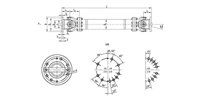
SWP-D Cardan Shaft
non-telescopic long
SWP-D non-telescopic long cross universal joint coupling adopts split bearing housing structure, transmits large torque with angular compensation, fixed overall length without axial expansion, widely applied for rolling mills and heavy transmission systems.
Universal joint cardan shafts, also commonly known as cardan drive shafts, are mechanical power transmission components designed to transfer rotary torque between two shafts whose centerlines are not perfectly aligned. They can accommodate angular misalignment, axial displacement and minor radial offset during operation, making them a flexible alternative to rigid shaft couplings. Unlike fixed transmission structures, cardan shafts maintain continuous rotation and torque delivery even when the relative position of driving and driven ends changes dynamically. This type of transmission element has been widely adopted in mechanical systems where rigid alignment is difficult to achieve or where positional variation occurs during equipment operation.
Classification and Common Types
Cardan shafts can be categorized according to structural configuration and functional layout. The single universal joint type contains only one cardan joint, which is suitable for systems with small angular deflection and simple motion requirements, though it produces non-uniform output rotation speed under large deflection angles. The double universal joint configuration is the most widely used form, equipped with two universal joints connected by an intermediate shaft. When properly arranged, this design can counteract the speed fluctuation generated by a single joint and achieve nearly constant angular velocity transmission. Telescopic cardan shafts feature a sliding spline section between the two joints, allowing adjustable effective length to compensate for axial distance variation between connected equipment. Fixed-length cardan shafts have a non-adjustable intermediate shaft and are applied in systems where the center distance between shafts remains stable. In addition, compact short-type cardan shafts are developed for confined installation spaces, while heavy-duty reinforced versions are built for high-torque continuous transmission scenarios.
Structural Composition and Materials
A typical double cardan shaft assembly consists of universal joint heads, cross spider assemblies, bearing sets, sealing components, intermediate shaft tubes, spline sleeves and connecting flanges or yokes. The cross spider sits at the core of each universal joint, linking two yokes and enabling pivoting movement in two perpendicular directions. Needle roller bearings are fitted between the cross spider and yoke bores to reduce friction during swinging motion. Seals protect bearing cavities from dust, moisture and abrasive contaminants and retain internal lubricant. The intermediate shaft tube is the main load-bearing part that transfers torque between two joints. Spline pairs on telescopic models provide sliding capacity while transmitting rotational force.
High-strength alloy steel is the dominant material for cross spiders, yokes and spline components, offering good fatigue resistance and load-carrying capacity under alternating torque. Intermediate tubes may use seamless steel tubing for general applications, and thicker-walled forged or welded structures for heavy-load conditions. Bearing rolling elements adopt wear-resistant bearing steel. Sealing parts are usually made of elastic polymer materials with stable performance across different temperature ranges. For special operating environments, surface treatment processes can be applied to improve corrosion and wear resistance of metal components.
Working Principle
Torque enters the cardan shaft through the driving yoke and passes to the cross spider, which drives the driven yoke to rotate. A single universal joint creates periodic speed variation: when the driving shaft rotates at a constant speed, the angular speed of the driven shaft fluctuates as the joint swings at an oblique angle. The degree of speed fluctuation rises along with the operating deflection angle.
The double cardan shaft eliminates this uneven rotation by phase arrangement. The two universal joints are installed so that the angular speed variation produced by the first joint is offset by the second joint. This arrangement requires the input shaft, intermediate shaft and output shaft to lie within a single plane, and the deflection angles of the two joints to be kept approximately equal. Telescopic structures work simultaneously with the joint mechanism: the spline pair slides freely to change the overall length of the shaft assembly while torque continues to transmit through the meshed spline teeth. In this way, the whole assembly adapts to combined angular and axial displacement during operation.
Features and Advantages
The primary advantage of cardan shafts is their outstanding capacity to compensate for multi-directional misalignment. They permit larger angular deflection than many standard flexible couplings and can handle combined angular and axial displacement in one unit. The structure delivers high torque density, so it can transmit heavy rotary power without excessive overall size. The rotational direction can be reversed freely without affecting transmission reliability.
Cardan shafts also show strong adaptability to dynamic positional changes. When connected equipment moves, vibrates or shifts during operation, the joints can swing to follow the movement without interrupting power transfer. Most configurations are easy to disassemble, inspect and replace wearing parts separately instead of changing the whole assembly. Compared with gear transmission systems for offset power delivery, cardan shaft arrangements often have simpler supporting structures and lower requirements for precision mounting bases. Properly lubricated and maintained units can sustain stable operation over long service cycles.
Limitations should also be noted. Larger deflection angles amplify vibration and stress on joint components. Unbalanced intermediate shafts may generate centrifugal vibration at high rotational speeds, and speed fluctuation risks remain if double joints are not correctly phased.
Applicable Working Conditions and Application Industries
Cardan shafts fit working conditions where driving and driven shafts cannot maintain permanent coaxial alignment, and where relative movement between connected machines occurs. They are suitable for both intermittent and continuous rotation, covering a wide range of torque and speed levels. Stable operation is achievable within a defined allowable swing angle; excessive deflection will shorten service life and increase vibration.
These drive components are found across multiple industrial sectors. In mobile machinery, they transfer power between prime movers and working attachments. In general industrial equipment, they connect separately mounted drive units and processing mechanisms. Material handling and conveying systems use cardan shafts to drive rotating components with floating mounting positions. Agricultural machinery relies on them to transmit power to field-working tools that move up and down during operation. Metallurgical, mining and construction equipment adopt heavy-duty cardan shafts for high-torque transmission under harsh dusty and impact-prone conditions. They are also used in test benches and special automation equipment where adjustable shaft spacing is required.
Installation and Commissioning Points
Before installation, all mating surfaces, spline teeth and bearing sealing areas should be cleaned to remove debris and residual processing contaminants. Check each joint for smooth pivoting without jamming or abnormal resistance. For double cardan shafts, the phase position of the two yokes must be aligned correctly to achieve approximate constant velocity output. When installing telescopic models, confirm the sliding stroke range to avoid overextension or compression that causes structural damage during operation.
Fasteners for flange or yoke connections need to be tightened evenly following a symmetrical sequence. After fastening, verify that the connection has no loose clearance. During commissioning, manually rotate the transmission chain first to check for interference, binding or abnormal friction. Start the equipment at low speed for a trial run, observe vibration level and noise, and check whether the swing range of universal joints stays within the allowable limit. Adjust mounting positions if obvious vibration or impact sound appears. After low-speed trial operation, gradually raise the operating speed and monitor temperature rise at joint bearing positions. Any sharp local temperature increase indicates abnormal loading or insufficient lubrication.
Selection and Customization
The core factors for selection include rated transmission torque, continuous operating speed, maximum required angular deflection, axial travel requirement and the mounting distance between driving and driven ends. Operating environment conditions such as ambient temperature, dust exposure and corrosive media also influence selection decisions. If the shaft needs to accommodate changing center distances, a telescopic type should be chosen. Where shaft spacing is fixed, a fixed-length design is more appropriate.
When standard configurations cannot satisfy site requirements, customized cardan shafts can be developed. Customization covers adjustment of overall length, flange or yoke connection forms, maximum allowable swing angle, spline specification and wall thickness of the intermediate tube. Reinforced structures can be designed for frequent shock loads. Special sealing or surface protection schemes are available for aggressive environments. The expected service duty cycle and startup frequency are also taken into account in custom design to match the actual load characteristics of the target system.
Operation and Maintenance
Regular lubrication is the most critical maintenance task. Lubricant should be replenished at specified intervals into the bearing cavities of universal joints. Lubrication frequency is shortened under heavy load, high speed or dusty conditions. Insufficient lubrication accelerates wear of cross spiders and needle bearings and may lead to early seizure of joints.
Routine inspection items include checking for oil leakage at sealing positions, loose connecting fasteners, abnormal vibration and noise during rotation. Check the clearance of spline sliding pairs and the pivoting flexibility of universal joints periodically. If excessive backlash, pitting or scoring is found on cross spider surfaces, bearing rollers or spline teeth, the worn parts need replacement in time. Avoid long-term operation at deflection angles exceeding the design limit. When the equipment is stored idle for a long period, rotate the cardan shaft at regular intervals to prevent local corrosion and lubricant stagnation inside bearing assemblies. After impact incidents or overload faults, conduct a full inspection of joint components before restarting the equipment. Timely maintenance reduces unexpected breakdowns and extends the working life of the cardan shaft assembly.