Ball-cage Universal Couplings
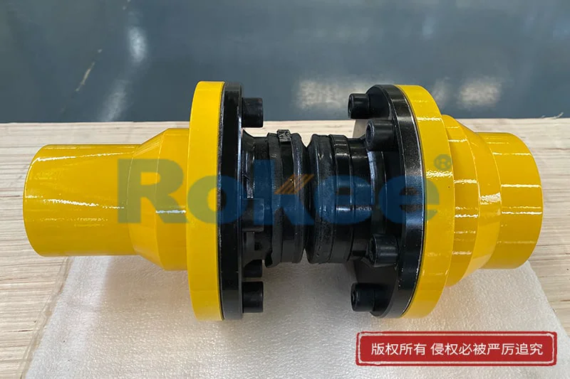
Ball-cage Universal Couplings (CV Cardan Shafts) for constant velocity torque transmission. Compensate angular & axial misalignment, smooth high-speed operation. Custom sizes, OEM available for machinery, metallurgy & automation. Rokee is a ball-cage universal couplings supplier in China. We support custom orders and offer direct factory sales, providing reliable products with flexible solutions for global clients.
Ball-cage universal couplings are constant-velocity transmission parts that transfer torque between misaligned shafts. Composed of inner and outer races, a ball cage, steel balls and seals, they mainly include fixed and plunging types. Torque is transmitted via rolling steel balls constrained by the cage, maintaining uniform rotary speed. Featuring compact size, high efficiency and good misalignment tolerance, they are widely used in machinery like conveyors and automated equipment. Proper installation, lubrication and regular inspection are essential for stable service.
-
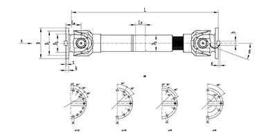
SWC-BH Cardan Shaft
Standard telescopic welded
SWC-BH universal shaft coupling with integral fork head, welded pipe structure and spline telescopic function. It compensates angular deflection and axial displacement for torque transmission, widely used in metallurgy, rolling mills and heavy machinery. -
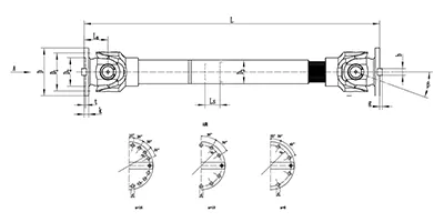
SWC-CH Cardan Shaft
long telescopic welded
SWC-CH long telescopic welded cross-shaft universal coupling adopts integral yoke structure, delivering reliable power transmission with both angular and long-range axial compensation. -
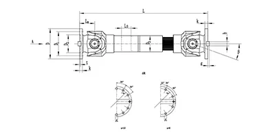
SWC-DH Cardan Shaft
Short Telescopic Welded
SWC-DH cross shaft universal coupling adopts integral yoke & welded pipe structure, featuring short telescopic spline for small axial displacement compensation. It allows large working angle, transmits torque steadily and efficiently, ideal for heavy industrial drives where shaft misalignment exists. -
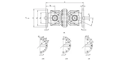
SWC-WD Cardan Shaft
Non-telescopic Short
SWC-WD cross shaft universal coupling is a non-telescopic short structure cardan coupling. It can only compensate angular displacement, features compact size, stable torque transfer and large allowable working angle, suitable for heavy-duty transmission systems with no axial movement requirement. -
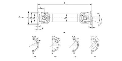
SWC-WH Cardan Shaft
Non-telescopic Welded
SWC-WH cross shaft universal joint coupling adopts welded pipe structure with no telescopic spline. It only compensates angular displacement, delivers stable torque transmission and allows large working angle. Suitable for heavy-duty drive systems where axial displacement is not needed. -
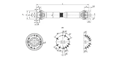
SWP-A Cardan Shaft
Long Telescopic
SWP-A type is a long telescopic cross shaft universal joint coupling (cardan shaft) with spline telescopic structure. It transmits torque between non-coaxial shafts, compensates angular deflection and axial length variation, widely used in metallurgy, lifting and other heavy machinery. -
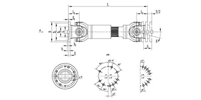
SWP-B Cardan Shaft
short telescopic
SWP-B type is a short telescopic cross shaft universal coupling (cardan shaft). Equipped with spline telescopic joint, it transfers torque between offset shafts, accommodates angular deflection and axial movement, widely used in metallurgy, mining and heavy equipment. -
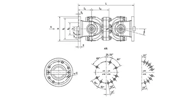
SWP-C Cardan Shaft
Non-telescopic Short
SWP-C type is a short non-telescopic cross shaft universal joint coupling (cardan drive shaft). It transmits torque between non-coaxial shafts and accommodates angular deflection only, suitable for heavy machinery with fixed axial installation distance. -
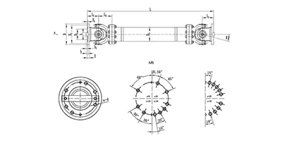
SWP-D Cardan Shaft
non-telescopic long
SWP-D non-telescopic long cross universal joint coupling adopts split bearing housing structure, transmits large torque with angular compensation, fixed overall length without axial expansion, widely applied for rolling mills and heavy transmission systems.
A ball-cage universal coupling is a type of constant-velocity motion transmission component designed to transfer rotary torque between two shafts with angular misalignment. Unlike traditional universal joints that produce fluctuating output speed under deflection angles, this coupling maintains nearly uniform rotational speed on the driven side. It belongs to the family of constant velocity joints and is widely adopted for power transmission where steady rotation must be preserved despite shaft offset and angular deviation. The core design relies on steel balls as rolling force-transferring elements contained within a cage assembly, which distinguishes it from other flexible and rigid coupling solutions. It bridges the gap between simple universal joints and precision gear couplings, offering balanced performance in misalignment tolerance and transmission stability.
Classification and Common Types
Ball-cage universal joint couplings can be sorted based on structural layout and movement characteristics. One major category is the fixed-type ball-cage coupling, which accommodates angular misalignment only without axial sliding between the two shaft halves. The second mainstream group is the plunging type, which permits both angular deflection and axial displacement during operation.
In terms of structural form, single-joint and double-joint configurations are available. A single ball-cage joint works for moderate angular misalignment. A double-joint assembly consists of two ball-cage units connected by an intermediate shaft, allowing larger total deflection angles and compensating for combined radial, angular and axial offset. Common variant designs differ in raceway profile, including arc track and straight track versions, each tuned for different motion requirements.
Structural Composition and Materials
The basic assembly of a ball-cage universal shaft coupling includes an outer race, an inner race, a ball cage, and a set of load-bearing steel balls. The outer race features precision-machined internal raceways, while the inner race carries matching external raceways. The ball cage sits between the two races, holding steel balls in designated pockets to keep them aligned along the correct force transmission plane and prevent ball crowding or dislocation under load. Sealing components and dust boots are normally fitted to block contaminants and retain internal lubricant.
High-strength alloy steel is the primary material for races, cage and rolling balls. These components undergo heat treatment to achieve high surface hardness and wear resistance while retaining sufficient core toughness to resist impact and fatigue cracking. Sealing elements are made of elastic polymer materials with good ageing resistance and oil compatibility. For special working environments, surface coating treatments may be applied to improve corrosion resistance.
Working Principle
Torque transmission depends on the contact force between steel balls and the paired raceways. When the driving shaft rotates, the inner race drives the steel balls, and the balls further push the outer race to rotate synchronously. The ball cage constrains all steel balls to stay on the bisecting plane of the angle formed by the driving shaft and driven shaft.
This geometric arrangement ensures that the contact points between balls and raceways always maintain equal effective rolling radii on both sides of the joint. As a result, the angular velocity of the driven shaft stays consistent with the driving shaft, eliminating the speed oscillation found in cross-type universal joints. For plunging-style structures, the steel balls can roll along the raceway direction to allow free axial sliding when the shaft distance changes, without interrupting steady torque transfer.
Features and Advantages
The most prominent merit of ball-cage cardan shafts is constant velocity output under angular misalignment. They can accept relatively large deflection angles compared with many other transmission couplings. Rolling contact between balls and raceways brings low friction loss, so transmission efficiency remains high during continuous operation.
The structure is compact in radial dimension, which suits installation spaces with limited radial room. The plunging variant offers built-in axial compensation capacity, removing the need for extra sliding sleeves in many layouts. The rolling contact design produces low running vibration and noise under balanced assembly. It also delivers stable performance under frequent forward and reverse rotation. Compared with gear couplings, it has simpler lubrication requirements and better tolerance to minor shaft alignment variation.
Applicable Conditions and Application Industries
This coupling is suitable for transmission systems where two connected shafts cannot be kept strictly coaxial and constant rotation speed is required. It handles steady torque as well as moderate cyclic load, but continuous heavy shock load should be avoided. The working environment should be controlled to prevent abrasive dust, chemical medium erosion and extreme temperature ranges that degrade seals and lubricants.
Typical application fields include material handling equipment, agricultural machinery, packaging machinery, conveyor drive systems, and mobile machinery transmission. It is also used in test benches, automation production lines and general power transmission equipment that requires compact constant-velocity joints.
Installation and Commissioning Points
Before installation, all mating surfaces, raceways and rolling elements must be cleaned to remove machining debris and foreign particles. Check all components for surface damage or deformation. The sealing boots should be inspected for cracks before assembly.
During mounting, shaft connection surfaces must have proper fit to avoid relative slipping under torque. The angular misalignment between shafts should be controlled within the permitted range of the selected coupling. Excessive deflection will accelerate wear and shorten service life. After positioning, fill the internal cavity with the specified lubricant. After initial assembly, manually rotate the coupling to confirm smooth movement without jamming or abnormal resistance.
For commissioning, run the equipment under no-load condition first and observe rotation smoothness. Check for abnormal noise, temperature rise or seal leakage. Gradually apply working load after confirming no abnormal behaviour. Recheck the fasteners and sealing status after the first period of running-in.
Selection and Customisation
Key factors for selection include rated torque requirement, maximum operating speed, expected angular deflection, required axial compensation stroke and mounting space dimensions. The peak torque during start-up and reversal should be considered rather than only the steady working torque. The installation method and connection form with adjacent shafts also affect the selection decision.
Standard products cover most general transmission demands. Customised solutions can be developed for special boundary conditions. Customisable items include connection configuration, overall size, allowable deflection angle, sealing structure and surface protection treatment. Custom design is carried out based on the provided transmission parameters and space constraints to match unique system layout demands.
Operation and Maintenance
Regular maintenance mainly focuses on lubrication and sealing inspection. Lubricant should be replenished or replaced according to operating cycle and working conditions. Degraded lubricant will increase wear rate of rolling contact surfaces. The sealing boots need routine inspection; damaged seals must be replaced promptly to stop dirt ingress and lubricant leakage.
Periodically check for abnormal vibration, noise and local overheating during operation. If excessive clearance develops or irregular rotation appears, disassembly inspection is required to assess wear of raceways, balls and the cage. Worn components should be replaced in time to prevent sudden coupling failure. Avoid prolonged overload operation and impact load beyond the allowable range. Store spare components in dry and clean conditions to prevent rust before use.