CV Universal Couplings
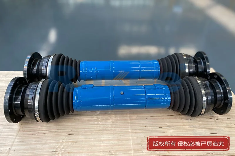
Reliable CV Universal Couplings manufacturer in China. Heavy load constant velocity universal couplings, durable & customizable universal joints for machinery, automotive & industrial power transmission. Rokee is a cv universal couplings supplier in China. We support custom orders and offer direct factory sales, providing reliable products with flexible solutions for global clients.
CV universal couplings, or constant velocity universal couplings, transmit torque between misaligned shafts without cyclic speed fluctuation. Main types include ball-cage and tripod structures, assembled with races, rolling elements, cages and elastic seals, mostly made of hardened alloy steel. By keeping rolling contact points on the angle bisector, they deliver steady rotation, low vibration and high efficiency. Widely used in machinery, transport and engineering equipment, they demand careful alignment during installation, plus regular seal and lubrication checks for reliable operation.
-
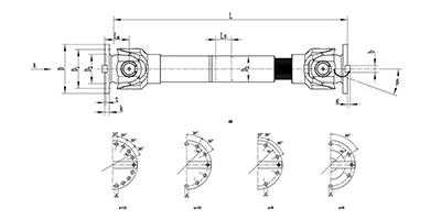
SWC-BH Cardan Shaft
Standard telescopic welded
SWC-BH universal shaft coupling with integral fork head, welded pipe structure and spline telescopic function. It compensates angular deflection and axial displacement for torque transmission, widely used in metallurgy, rolling mills and heavy machinery. -
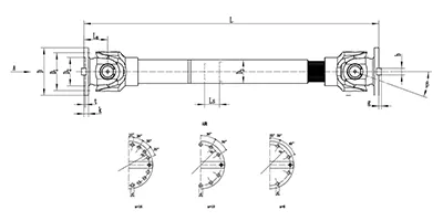
SWC-CH Cardan Shaft
long telescopic welded
SWC-CH long telescopic welded cross-shaft universal coupling adopts integral yoke structure, delivering reliable power transmission with both angular and long-range axial compensation. -
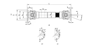
SWC-DH Cardan Shaft
Short Telescopic Welded
SWC-DH cross shaft universal coupling adopts integral yoke & welded pipe structure, featuring short telescopic spline for small axial displacement compensation. It allows large working angle, transmits torque steadily and efficiently, ideal for heavy industrial drives where shaft misalignment exists. -
SWC-WD Cardan Shaft
Non-telescopic Short
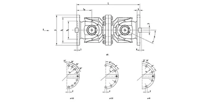
SWC-WD cross shaft universal coupling is a non-telescopic short structure cardan coupling. It can only compensate angular displacement, features compact size, stable torque transfer and large allowable working angle, suitable for heavy-duty transmission systems with no axial movement requirement. -
SWC-WH Cardan Shaft
Non-telescopic Welded
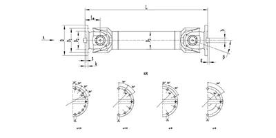
SWC-WH cross shaft universal joint coupling adopts welded pipe structure with no telescopic spline. It only compensates angular displacement, delivers stable torque transmission and allows large working angle. Suitable for heavy-duty drive systems where axial displacement is not needed. -
SWP-A Cardan Shaft
Long Telescopic
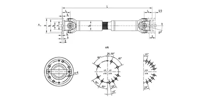
SWP-A type is a long telescopic cross shaft universal joint coupling (cardan shaft) with spline telescopic structure. It transmits torque between non-coaxial shafts, compensates angular deflection and axial length variation, widely used in metallurgy, lifting and other heavy machinery. -
SWP-B Cardan Shaft
short telescopic
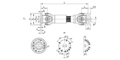
SWP-B type is a short telescopic cross shaft universal coupling (cardan shaft). Equipped with spline telescopic joint, it transfers torque between offset shafts, accommodates angular deflection and axial movement, widely used in metallurgy, mining and heavy equipment. -
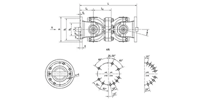
SWP-C Cardan Shaft
Non-telescopic Short
SWP-C type is a short non-telescopic cross shaft universal joint coupling (cardan drive shaft). It transmits torque between non-coaxial shafts and accommodates angular deflection only, suitable for heavy machinery with fixed axial installation distance. -
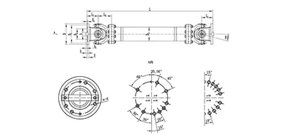
SWP-D Cardan Shaft
non-telescopic long
SWP-D non-telescopic long cross universal joint coupling adopts split bearing housing structure, transmits large torque with angular compensation, fixed overall length without axial expansion, widely applied for rolling mills and heavy transmission systems.
CV universal couplings, also known as constant velocity universal couplings, belong to a family of motion transmission components designed to transfer rotary torque between two shafts that are not perfectly aligned on a single axis. Unlike ordinary universal joints that produce fluctuating output rotational speed under an angular offset, constant velocity variants maintain a uniform angular velocity relationship between the driving side and the driven side throughout rotation. This core feature eliminates periodic speed variation, vibration and secondary inertial loads caused by speed unevenness. These couplings serve as a flexible transmission medium to accommodate shaft misalignment while reliably delivering continuous rotary power, and they have become essential components for power transmission systems requiring stable rotation under offset conditions.
Classification and Common Types
CV universal shaft couplings can be sorted by structural forms and motion compensation characteristics. One major category is ball-type constant velocity couplings, which rely on steel balls as rolling transmission elements. Another widely used group is tripod constant velocity couplings that adopt three roller assemblies for torque transfer. In addition, there are double-offset constant velocity couplings and disc-type constant velocity couplings for special offset requirements.
In practical application, several typical structural configurations are frequently adopted. Fixed ball cage CV couplings mainly handle fixed angular misalignment with limited axial sliding. Sliding ball cage CV couplings can simultaneously compensate for angular deviation and axial displacement through the sliding movement of the ball cage along the shaft. Tripod plunging couplings excel at absorbing relatively large axial movements together with small angular offsets. Combined types integrate the features of fixed and sliding structures to meet compound misalignment demands. Each type has its own preferred working range of deflection angle and axial compensation capacity, and users select forms according to the actual offset state of paired shafts.
Structural Composition and Materials
A standard CV universal joint coupling assembly consists of several core parts. The main components include an outer race, an inner race, rolling transmission elements such as steel balls or tripod rollers, a ball cage or retainer, shaft connecting hubs, sealing boots and fastening accessories. The outer race features precision-machined raceway grooves that match the contour of rolling elements, while the inner race connects directly with one transmission shaft and carries the other set of raceways. The retainer or cage constrains the rolling elements to keep them in the correct working position and prevents dislocation during rotation. Sealing components wrap the moving contact zones to block dust, moisture and foreign debris.
High-strength alloy steel is the primary material for load-bearing parts including races, rolling balls and rollers. These materials are processed with surface hardening treatments to achieve high contact hardness, wear resistance and fatigue resistance under repeated rolling contact stress. The cage and retainer parts may use alloy steel or high-performance engineering polymers for certain light-load scenarios. Sealing boots are usually made of elastic rubber or thermoplastic elastomers with good low-temperature flexibility and aging resistance. Connecting hubs can be manufactured from carbon steel or alloy steel depending on torque load level.
Working Principle
The fundamental working principle of CV cardan couplings is to keep the contact points of rolling elements always located on the bisecting plane of the angle formed by the driving shaft and driven shaft. When two connected shafts form an angular offset, the raceway geometry guides rolling elements to roll along predefined curved tracks. With the constraint of the cage, every rolling contact point divides the included angle between input and output shafts equally. Under this geometric condition, the instantaneous rotational speed of the driven shaft stays identical to that of the driving shaft at any rotation position.
For sliding-style CV couplings, relative axial movement between inner and outer races is allowed along the raceway direction while the constant velocity relationship remains valid. Tripod couplings transmit torque via rollers rolling in longitudinal grooves of the outer housing; the self-adjustment of roller positions realizes constant velocity output under angular offset and axial sliding. During operation, rolling contact replaces sliding friction to reduce frictional loss and heat accumulation compared with simple hinged universal joints.
Features and Advantages
The most prominent advantage of CV cardan shaft couplings is the constant velocity transmission performance. There is no cyclic speed fluctuation on the output side within the allowable deflection range, which greatly reduces torsional vibration, noise and dynamic impact on downstream equipment. These couplings can accommodate combined misalignment, including angular offset, axial displacement and minor radial offset in many designs.
They have compact overall dimensions relative to the torque they transmit, which facilitates layout in confined installation spaces. Rolling contact inside the coupling brings low friction torque and high transmission efficiency during continuous operation. Good fatigue performance enables long service life under cyclic torque loads. Compared with multiple ordinary universal joint combinations used to approximate constant velocity, a single CV coupling assembly simplifies the transmission structure and reduces the number of supporting parts. Many designs support bidirectional rotation and can operate steadily under forward and reverse switching working conditions.
Limitations also exist. The allowable maximum deflection angle is lower than that of conventional universal joints. Precision machining requirements for raceways and rolling elements raise manufacturing accuracy standards, and sealing structures need regular inspection to avoid lubricant leakage and premature wear.
Applicable Working Conditions and Application Industries
CV universal couplings suit working scenarios where rotary power must be transmitted between offset shafts and uniform output speed is mandatory. They adapt to continuous or intermittent rotation, steady torque and moderate impact torque within rated capacity. Operating temperature should stay within the applicable range of sealing materials and lubricants. Excessive deflection beyond design limits, severe abrasive dust environment or sustained heavy shock loads will shorten service life unless customized protective structures are adopted.
They are widely deployed in multiple industrial sectors. Transportation equipment uses these couplings for power transmission between offset drive components. Automated machinery and production lines apply them in rotary conveying and driving modules. Engineering machinery adopts them for power delivery between mobile, misaligned drive shafts. Agricultural machinery fits CV couplings into variable-position transmission systems on harvesting and tillage devices. Specialized test equipment, robotic motion axes and mobile power platforms also select constant velocity couplings to guarantee stable rotary motion under changing shaft positions.
Installation and Commissioning Guidelines
Before installation, inspect all components to check for surface damage, deformation and completeness of sealing parts. Clean the matching surfaces of shafts, inner bores and raceways thoroughly to remove dirt, metal chips and residual impurities. Appropriate lubricant should be filled into the internal raceway cavity according to design requirements before assembly.
Align the two connected shafts as closely as possible to minimize the actual operating deflection angle, even though the coupling can tolerate misalignment. Install hubs onto shaft ends with proper interference or key connection, and apply specified tightening force for fasteners to prevent circumferential slipping. After the coupling assembly is in place, fit and clamp sealing boots carefully to ensure a closed protective cavity.
Upon initial commissioning, perform a no-load trial run first. Monitor running noise, temperature rise and sealing status. If abnormal noise or obvious local heating appears, stop operation and recheck shaft alignment, fastening torque and sealing installation. Gradually add working load only after stable no-load operation is confirmed. Avoid forced prying or hammer impact directly on raceway and rolling element components during installation, as impact damage will destroy precision race surfaces.
Selection and Customization
The core basis for standard selection includes rated transmission torque, peak torque under impact conditions, maximum working deflection angle, required axial compensation stroke, rotating speed and installation space dimension constraints. The operating cycle and working temperature also affect model screening. It is necessary to reserve a reasonable safety margin against transient overload torque in practical systems.
When standard products cannot satisfy working demands, customized development is available. Customizable items include adjusting the maximum allowable deflection angle, extending axial sliding stroke, modifying connection forms of shaft hubs, upgrading sealing structures for dusty or humid environments, optimizing internal lubrication channels and adjusting overall size to fit limited installation envelopes. Custom schemes require clear definition of all boundary conditions of the transmission system to match structural strength and kinematic performance.
Operation and Maintenance
Regular maintenance focuses on sealing integrity and lubrication status, which are decisive factors for service life. Periodically check sealing boots for cracks, aging and grease leakage. Once seal failure occurs, foreign particles will enter raceways and cause accelerated abrasion of rolling elements and race surfaces.
Lubricant should be replenished or replaced following the prescribed maintenance interval. Old deteriorated grease mixed with impurities needs full removal before refilling fresh lubricant. During routine inspection, listen for abnormal grinding or knocking sound during rotation, which indicates wear of internal rolling parts or loose connection.
If disassembly is required for inspection, mark the relative assembly position of components to preserve the original matching relationship. Avoid mixing rolling elements from different sets. Worn raceways, cracked cages or pitted rolling elements should be replaced rather than reused. When the coupling has been exposed to heavy overload or collision events, a comprehensive internal inspection is necessary before putting it back into service. Store spare couplings in dry environments with protective coating to prevent rust on precision race surfaces.