In the modern mechanical transmission industry, coupling components serve as essential connecting units that link two rotating shafts to transmit torque and rotational motion, ensuring the synchronized operation of diverse mechanical equipment. Among various coupling types, diaphragm couplings have gained extensive popularity in high-precision and high-efficiency transmission systems by virtue of their unique elastic deformation mechanism, excellent mechanical stability and reliable environmental adaptability. As a kind of all-metal flexible coupling, diaphragm couplings rely on the elastic deformation of metal diaphragms to compensate for shaft misalignment, achieving torque transmission without mechanical clearance. Compared with traditional elastic couplings that adopt non-metal elastic elements, diaphragm couplings eliminate the aging and fatigue defects of polymer materials, and maintain stable working performance under extreme working conditions such as high temperature, low temperature and chemical corrosion. This article elaborates on the structural composition, core performance characteristics, mainstream classification forms and diverse application scenarios of diaphragm couplings, providing an in-depth interpretation of the intrinsic value and application advantages of this mechanical transmission component in industrial production.

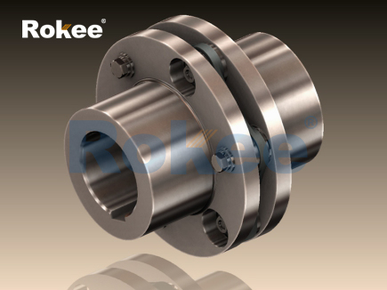
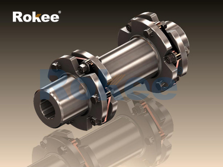
The basic structure of a diaphragm coupling presents a compact and rigorous mechanical combination, which is mainly composed of metal diaphragms, connecting bolts, shaft sleeves and intermediate sleeves. The metal diaphragm is the core functional component of the coupling, usually made of high-strength stainless steel materials with uniform thickness and smooth surface. Most diaphragms are designed into irregular sheet structures with special contour curves, which can produce controllable elastic deformation under external force. In most industrial configurations, multiple thin diaphragms are stacked in an orderly manner to form a diaphragm group, and the stacked structure effectively enhances the overall deformation resistance and torque bearing capacity while maintaining flexible elasticity. Connecting bolts are indispensable fastening parts, which adopt high-strength metal structures to fix the diaphragms and shaft sleeves tightly. The bolt arrangement follows a symmetrical circumferential distribution rule to ensure uniform force on each connection point and avoid local stress concentration during high-speed rotation. The shaft sleeve is the assembly structure that closely fits with the rotating shaft, with a smooth and precise inner hole to realize interference fit or gapless connection with the shaft body, ensuring zero relative sliding between the coupling and the shaft during operation. For long-distance transmission equipment, intermediate sleeves are added between two sets of diaphragm groups. The intermediate sleeve is usually made of high-rigidity metal materials, which can extend the transmission distance and further optimize the misalignment compensation range without reducing the overall structural stability. All components of the diaphragm coupling are assembled through mechanical fastening without any welding or adhesive connection, which simplifies the later disassembly, maintenance and replacement procedures and improves the reusable rate of parts.
The unique structural design endows diaphragm couplings with superior and comprehensive mechanical performance, covering misalignment compensation capability, torsional rigidity, rotational stability and environmental adaptability. In terms of misalignment compensation, diaphragm couplings can simultaneously adapt to three common shaft misalignment states in mechanical operation, including axial displacement, radial deviation and angular deflection. The elastic deformation of metal diaphragms can subtly offset the position deviation between the driving shaft and the driven shaft, avoiding additional mechanical stress caused by misalignment. Single-layer diaphragm structures are more suitable for working conditions with small angular deviation, while multi-layer stacked diaphragms have stronger comprehensive compensation capacity and can cope with complex superposition of multiple deviations. In terms of torsional rigidity, all-metal materials and compact assembly structures enable the coupling to maintain low torsional deformation under rated torque. This high torsional rigidity ensures that the coupling will not produce obvious angular distortion during torque transmission, realizing accurate and synchronous rotation of the connected shafts, which is particularly critical for precision transmission equipment that requires strict motion control. In terms of rotational performance, the symmetrical structural layout and uniform material distribution make the coupling have excellent dynamic balance. It can maintain stable operation under high-speed rotating conditions without obvious vibration and noise, and the optimized structural design effectively reduces rotational inertia, lowering the energy consumption of equipment during starting and accelerating processes. In addition, diaphragm couplings have outstanding environmental adaptability. Different from couplings with rubber and plastic elastic parts, all-metal components will not undergo aging, deterioration or deformation due to temperature changes. They can work stably in high-temperature environments with intense heat radiation and low-temperature environments with cold condensation, and also resist the corrosion of common chemical media such as oil and weak acid liquid in industrial production. Meanwhile, the internal connection mode of the coupling is completely gapless, which eliminates the return clearance during torque transmission and ensures high-precision motion feedback in forward and reverse rotation.
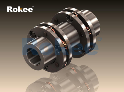
According to structural differences and functional characteristics, diaphragm couplings can be divided into multiple classification types, and the most common classification standard is based on the number of diaphragm groups and structural combination forms. Single diaphragm coupling is the simplest structural type, which consists of a single set of diaphragm components and two shaft sleeves. This coupling has a compact overall size, light weight and low rotational inertia, and is suitable for small-torque and high-speed transmission scenarios. Its structural characteristics determine that it has limited compensation capacity, especially for radial deviation, so it is mostly applied to precision micro-transmission equipment with high installation accuracy and small misalignment range. Double diaphragm coupling is the most widely used structural form in the industry. It is composed of two independent diaphragm groups and an intermediate connecting sleeve. The intermediate sleeve separates the two diaphragm groups, and the cooperative deformation of the double diaphragms greatly improves the comprehensive misalignment compensation ability. This type of coupling can bear medium and high torque loads, and has balanced performance in rigidity, elasticity and stability, adapting to most conventional industrial transmission equipment. In addition, there are multi-section diaphragm couplings with complex combined structures. This kind of coupling adopts multiple intermediate sleeves and multi-group diaphragm series connection, which is specially designed for long-distance shaft transmission. It can maintain excellent compensation performance under the condition of large shaft spacing, and its high structural rigidity can avoid bending vibration of the long shaft body during operation. According to the diaphragm processing technology, it can also be divided into integral thin-piece diaphragms and split combined diaphragms. Integral diaphragms are integrally formed by precision stamping, with uniform internal stress and long service life; split combined diaphragms are assembled by multiple small metal sheets, which have stronger deformation toughness and are more suitable for working conditions with frequent alternating loads.
Diaphragm couplings are widely used in various industrial fields relying on their superior comprehensive performance, covering precision manufacturing, energy power, transportation and heavy machinery industries. In the field of precision manufacturing and automated production, this kind of coupling is applied to servo transmission systems, precision processing machine tools and automated manipulators. The zero-backlash transmission characteristic and high positioning accuracy ensure that the equipment can complete micro-displacement control and repeated positioning actions stably. The low vibration and low noise operation state also avoid processing errors caused by mechanical vibration, improving the processing precision of workpieces. In the energy and power industry, diaphragm couplings are installed in power generation equipment, water pump units and ventilation equipment. These devices often run continuously for a long time with stable torque requirements. The all-metal structure can withstand long-term cyclic load impact, and the maintenance-free operation mode reduces the downtime caused by parts replacement. In the petrochemical industry, production equipment often contacts corrosive media and works in high-temperature sealed environments. The corrosion resistance and temperature adaptability of diaphragm couplings enable them to operate stably in harsh chemical production conditions, avoiding component damage caused by medium erosion. In the field of heavy engineering machinery, large transmission equipment such as mining machinery and metallurgical equipment needs to bear heavy torque and harsh vibration interference. Multi-layer thickened diaphragm couplings are selected for such equipment, which rely on high torsional rigidity and strong load-bearing capacity to realize stable transmission of heavy loads. Besides, diaphragm couplings also have important application value in the transportation industry, being used in auxiliary transmission systems of transportation equipment to ensure the smooth power transmission of power components.
In actual industrial application, the service life and operating effect of diaphragm couplings are affected by installation accuracy and working conditions. Excessive shaft misalignment beyond the allowable compensation range will cause continuous fatigue deformation of diaphragms, accelerating metal fatigue and crack generation. Therefore, precise alignment calibration is required during installation to control the deviation within the rated range. Although all-metal diaphragms have good durability, long-term operation under extreme alternating loads will still produce tiny fatigue marks. Regular equipment inspection is conducive to timely detection of diaphragm deformation and fatigue damage. In addition, the surface of metal components should be kept clean and dry to avoid long-term adhesion of corrosive impurities, so as to maintain the surface integrity of diaphragms and fastening parts. Compared with other flexible couplings, the only limitation of diaphragm couplings is the higher requirement for installation precision and processing technology, which makes the manufacturing cost relatively higher than ordinary elastic couplings. However, considering the long service life, maintenance-free characteristics and stable high-precision transmission performance, its comprehensive use cost has obvious advantages in the long-term operation cycle of industrial equipment.
With the continuous upgrading of industrial manufacturing technology and the gradual improvement of mechanical transmission precision requirements, diaphragm couplings are constantly optimized in structural design and material application. The development direction of diaphragms tends to be thinner in single layer, higher in stacking density and more reasonable in contour radian, which further balances the relationship between flexibility and rigidity. The continuous innovation of high-strength alloy metal materials also improves the fatigue resistance and corrosion resistance of couplings. In the future industrial transmission system, diaphragm couplings will further expand their application scope, gradually replacing traditional low-precision couplings in more high-end manufacturing fields. As a key basic mechanical component, diaphragm couplings will continue to rely on their unique structural advantages and stable performance to provide reliable guarantee for the efficient and safe operation of modern mechanical equipment, and become an indispensable important part of the industrial transmission chain.
pu sandwich panel line,pu sandwich panel machine,sandwich panel machine
« Diaphragm Couplings » Latest Update Date: May 8, 2026
https://www.rokeecoupling.net/tags/diaphragm-couplings.html