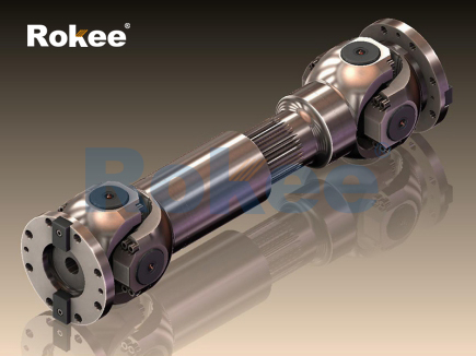
In modern mechanical transmission systems, the efficient transfer of rotational torque and linear displacement compensation stands as one of the core requirements for stable equipment operation, and telescoping driveshafts have emerged as an indispensable mechanical component to meet such comprehensive functional demands. A telescoping driveshaft refers to a specialized transmission shaft structure with an extensible and retractable mechanical design, which can freely adjust its overall axial length within a preset range while continuously and stably transmitting rotational power. Unlike conventional fixed-length driveshafts that maintain a constant structural dimension during operation, this adjustable shaft structure effectively adapts to the dynamic spatial changes between power output components and load-bearing components, resolving the transmission obstacles caused by relative displacement, angle deviation and spatial vibration in mechanical motion systems. Its unique structural characteristics and mechanical performance make it widely applicable in mobile mechanical equipment, industrial transmission devices and special engineering machinery, delivering reliable power transmission guarantees for various complex operating working conditions.
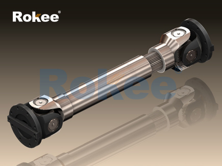
The basic working principle of a telescoping driveshaft originates from the mechanical matching of nested sliding structures, which combines the torque transmission capability of a solid shaft with the axial displacement flexibility of a sliding pair. The core structural composition generally includes an outer shaft sleeve, an inner sliding shaft, a motion limiting assembly and a vibration damping auxiliary structure. The inner sliding shaft is precisely embedded inside the outer shaft sleeve, and the contact part between the two components adopts a special engagement structure to ensure synchronous rotation while allowing free axial sliding. During the power transmission process, rotational torque is transferred from the driving end to the outer shaft sleeve, and then evenly transmitted to the inner sliding shaft through the engagement structure, ultimately driving the load equipment to operate synchronously. When the spatial distance between the power source and the load changes due to mechanical vibration, component deformation or working position adjustment, the inner shaft and the outer sleeve automatically slide relative to each other to complete length compensation, avoiding mechanical jamming, shaft deformation or power transmission interruption caused by fixed shaft spacing. The motion limiting assembly is installed at the connection gap of the nested structure to control the maximum telescoping stroke, preventing structural separation caused by excessive sliding and ensuring the overall structural integrity during long-term cyclic operation.
The internal engagement structure determines the torque transmission efficiency and sliding smoothness of the telescoping driveshaft, and the most commonly applied structural forms include spline engagement and polygonal sliding matching. Spline engagement structures are processed with evenly distributed tooth grooves on the outer surface of the inner shaft and the inner wall of the outer sleeve. The mutually meshed tooth profiles can disperse torque evenly on each contact tooth surface, reducing local stress concentration and improving the torsional bearing capacity of the component. This structure features high transmission accuracy and small rotational clearance, which is suitable for mechanical systems requiring precise power output and low vibration operation. Polygonal sliding matching usually adopts hexagonal or octagonal cross-section designs for the inner shaft and outer sleeve. The smooth polygonal contact surfaces simplify the processing technology and reduce the friction resistance during axial sliding. Although its torsional rigidity is slightly lower than that of spline structures, it has obvious advantages in low-load and frequent telescoping working scenarios. In order to further optimize the sliding performance, the matching gap between the nested shafts is strictly controlled within a tiny range during processing, and the surface is treated with smoothing and anti-friction treatment to minimize mechanical wear caused by frequent relative movements.
Material selection is a critical factor affecting the service life and comprehensive performance of telescoping driveshafts, and the selection criteria mainly focus on mechanical strength, wear resistance, fatigue resistance and structural ductility. High-strength alloy steel is the most widely used base material for heavy-duty telescoping driveshafts. It has excellent tensile strength and torsional resistance, and can maintain stable structural performance under high torque and heavy load conditions. After forging and heat treatment processes such as quenching and tempering, the alloy steel shaft body can effectively resist structural deformation and metal fatigue caused by long-term cyclic rotation and frequent telescoping movements. For light-load and low-speed transmission equipment, high-quality carbon steel is often adopted to balance mechanical performance and manufacturing cost. In some special working environments with strict weight limitation requirements, lightweight metal alloys are applied to produce telescoping driveshafts. This type of material reduces the overall weight of the transmission assembly without losing basic torsional performance, which helps to lower the energy consumption of mechanical operation. In addition to metal base materials, auxiliary functional materials such as high-temperature resistant lubricating grease and wear-resistant sealing gaskets are indispensable. The lubricating medium fills the matching gap of the nested structure to reduce dry friction between metal surfaces, while the sealing gaskets can block external dust, moisture and corrosive substances from entering the internal sliding gap.
In terms of mechanical performance characteristics, telescoping driveshafts possess multiple functional advantages that fixed-length driveshafts cannot match. The most prominent advantage is the active length compensation capability, which can adapt to the axial displacement generated by mechanical operation within the designed stroke range. In vehicle traveling systems and mobile engineering equipment, the vibration of the chassis and the jitter of the suspension structure will cause real-time changes in the relative distance between the power engine and the driving axle. The telescoping structure can automatically adjust the shaft length to keep the transmission connection stable, avoiding additional mechanical stress on the shaft body. Secondly, the reasonable nested structural design has good vibration damping and buffering effects. The tiny gaps between the nested components and the lubricating medium inside can absorb part of the vibration energy generated during torque transmission, reducing the vibration amplitude of the transmission system and lowering mechanical noise. Moreover, the segmented nested structure simplifies the overall disassembly and assembly process. When routine maintenance or component replacement is required, the telescoping driveshaft can be disassembled without dismantling the entire transmission system, which effectively reduces maintenance difficulty and time cost. It is also necessary to recognize the inherent limitations of this component. Compared with integrated fixed-length shafts, the nested structure has more contact gaps, which leads to slightly lower overall structural rigidity. Under extreme high-load and high-speed operating conditions, minor rotational clearance may occur, so it is not suitable for ultra-high-precision static transmission scenarios without displacement changes.
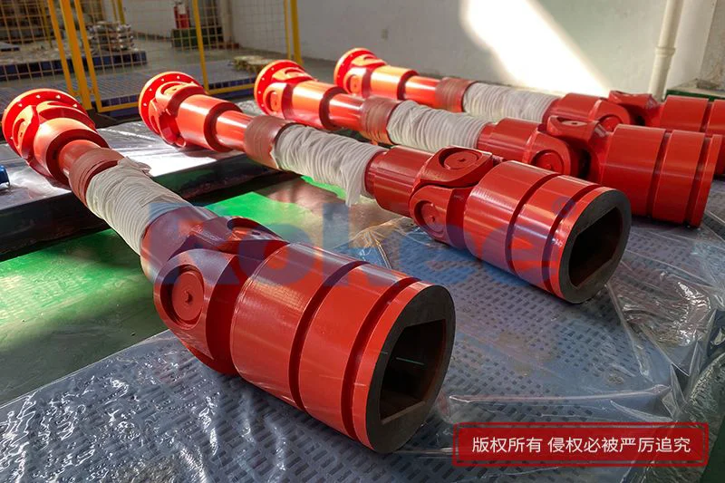
Telescoping driveshafts have a wide coverage of application scenarios, involving multiple fields such as transportation machinery, industrial production equipment and special engineering devices. In the transportation machinery industry, they are commonly used in the power transmission systems of off-road vehicles, engineering vehicles and agricultural machinery. These vehicles often drive on uneven road surfaces, and the chassis structure will produce continuous jitter and displacement during driving. The telescoping driveshaft can adapt to the dynamic changes of the chassis space to ensure stable power transmission from the power unit to the walking mechanism. In industrial production, this type of driveshaft is applied to automated conveying equipment, lifting machinery and rotating processing devices. For mechanical equipment with adjustable working positions, the telescoping function can compensate the position deviation generated by mechanical movement, maintaining the synchronization of power transmission. In addition, telescoping driveshafts are also used in aerospace auxiliary transmission structures, hydraulic power devices and marine auxiliary mechanical systems. In complex working environments such as high altitude, humidity and salt corrosion, optimized structural sealing and material modification treatments can ensure their long-term stable operation.
The manufacturing and processing technology of telescoping driveshafts requires high precision to meet the matching accuracy and mechanical performance requirements of nested components. The processing flow usually includes raw material forging, rough turning finishing, precision tooth profile or cross-section processing, surface heat treatment, anti-corrosion coating and assembly debugging. The forging process optimizes the internal metal fiber structure of the shaft body to improve the overall toughness and compressive resistance. Precision machining equipment is used to control the dimensional tolerance of the inner shaft and outer sleeve within a micron level, ensuring the smoothness of relative sliding without excessive shaking or jamming. After finishing processing, the surface of the shaft body is subjected to quenching treatment to improve surface hardness and wear resistance, and then polished and coated with anti-rust materials to enhance environmental adaptability. During the assembly process, professional equipment is used to detect the telescoping flexibility and torsional uniformity of the finished product. Unqualified products with excessive sliding resistance and uneven torque transmission are screened out to ensure that each finished product meets the mechanical operation standards. With the continuous upgrading of mechanical processing technology, intelligent machining and precision mold casting technologies have been gradually applied to the production of telescoping driveshafts, which further improves production efficiency and structural consistency of products.
Daily maintenance and rational use are key to extending the service life of telescoping driveshafts, and most component failures are caused by improper maintenance and harsh operating conditions. The most common failure forms include surface wear of sliding matching surfaces, lubricant deterioration, sealing structure aging and shaft body fatigue deformation. In daily use, regular inspection of the sealing gaskets at both ends of the driveshaft is required to check for aging, cracking and falling off, so as to prevent external impurities from entering the internal sliding gap and causing abrasive wear of the metal contact surface. It is necessary to replace the internal lubricating medium regularly according to the operating frequency and working environment. The deteriorated lubricant will lose its anti-friction and heat dissipation effects, which may lead to increased sliding resistance and local high-temperature abrasion. During the operation of mechanical equipment, long-term overload operation should be avoided. Excessive torque will cause permanent deformation of the nested structure and tooth surface damage, resulting in increased rotational clearance and reduced transmission efficiency. For the driveshafts working in humid and corrosive environments, regular surface cleaning and anti-corrosion maintenance are needed to remove surface attachments and prevent chemical corrosion from damaging the shaft body structure.
With the continuous development of modern mechanical engineering towards high efficiency, energy saving and intelligentization, the technical optimization direction of telescoping driveshafts is gradually clear. In terms of material research and development, new composite metal alloys and high-strength lightweight materials are being continuously explored to reduce structural weight while improving fatigue resistance and corrosion resistance, adapting to the lightweight development trend of mobile mechanical equipment. In structural optimization, the bionic tooth profile and integrated damping structure design are adopted to reduce rotational clearance and vibration amplitude, further improving transmission accuracy and operational stability. In terms of intelligent monitoring, built-in sensing components are being combined with the driveshaft structure to monitor the telescoping stroke, operating temperature and torque load in real time, realizing early warning of abnormal wear and structural failure. In addition, the simplification of processing technology and the optimization of assembly structure will effectively reduce manufacturing and maintenance costs, making telescoping driveshafts more widely used in medium and low-end mechanical equipment. In the future, with the progress of interdisciplinary technologies such as material science and intelligent sensing, the comprehensive performance of telescoping driveshafts will be further improved, and they will play a more critical role in complex and diversified mechanical transmission systems.
As a functional transmission component integrating length compensation and torque transmission, telescoping driveshafts have irreplaceable application value in the mechanical industry. Their unique nested sliding structure solves the spatial adaptation problem of traditional fixed-length transmission shafts, and the reasonable material selection and processing technology ensure stable mechanical performance in complex working conditions. From simple industrial conveying machinery to heavy-duty engineering vehicles and special aerospace equipment, telescoping driveshafts provide reliable power connection guarantees for various mechanical systems. While continuously optimizing structural performance and processing technology, the industry also needs to pay attention to standardized maintenance and scientific application to maximize the service life and operational efficiency of components. In the context of the rapid development of modern mechanical engineering, the continuous technological iteration and performance upgrading of telescoping driveshafts will surely promote the further improvement of mobile transmission system technology, laying a solid foundation for the diversification and high-efficiency development of mechanical equipment.
pu sandwich panel line,pu sandwich panel machine,sandwich panel machine
« Telescoping Driveshafts » Latest Update Date: May 9, 2026
https://www.rokeecoupling.net/tags/telescoping-driveshafts.html