A barrel coupling assembly drawing is a detailed technical document that serves as a critical guide for the manufacturing, assembly, inspection, and maintenance of barrel couplings, which are essential mechanical components used to connect two shafts in various industrial applications. These drawings translate abstract design concepts into precise, visual instructions that ensure every component of the barrel coupling fits together correctly, functions as intended, and meets the required performance standards. Unlike simple part drawings, an assembly drawing focuses on the relationships between individual components, showing how they interact, align, and work together to form a complete, functional barrel coupling. The accuracy and clarity of such drawings are paramount, as even minor discrepancies can lead to assembly errors, reduced performance, premature wear, or even catastrophic failure in the machinery where the coupling is installed.
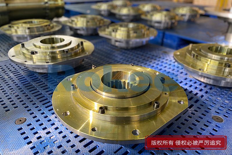
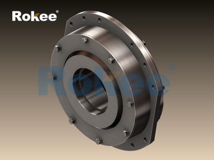
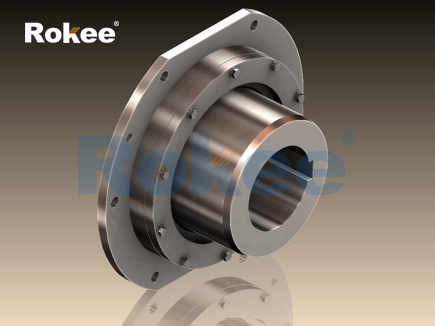
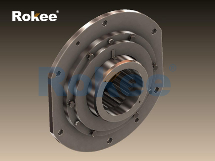
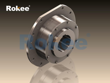
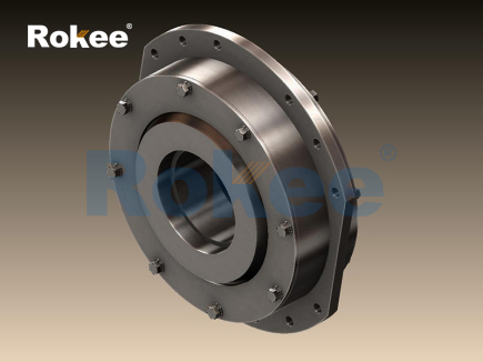
At its core, a barrel coupling assembly drawing must comprehensively represent all the components that make up the coupling, including the sleeve, hub, barrels, covers, seals, retaining rings, and any fasteners or auxiliary parts. Each component is depicted with precise dimensions, tolerances, and material specifications, ensuring that manufacturers can produce parts that fit together seamlessly. The drawing must also illustrate the correct orientation of each component, the sequence of assembly, and any critical alignment requirements. For example, the sleeve—typically a cylindrical component with internal semicircular toothing—and the hub—with matching external toothing—must be aligned such that the cylindrical barrels, which act as the primary torque-transmission elements, fit securely into the spaces formed by the toothing. This alignment is critical because the barrels must be able to rotate freely within these spaces to compensate for angular misalignments and axial displacements between the connected shafts.
The process of creating a barrel coupling assembly drawing begins with a thorough understanding of the coupling’s design requirements and intended application. Engineers must first define the performance parameters of the coupling, such as the maximum torque it needs to transmit, the allowable angular misalignment and axial displacement, the operating temperature range, and the environmental conditions it will be exposed to. These parameters directly influence the design of each component, from the material selection to the dimensions and tolerances. For instance, couplings used in heavy-duty applications like crane lifting mechanisms or winch conveyors must be designed to withstand large radial loads and high torque, requiring robust materials and precise manufacturing tolerances. In contrast, couplings used in lighter industrial applications may have less stringent requirements, allowing for more cost-effective materials and slightly looser tolerances.
Material selection is a key consideration in the design of a barrel coupling, and this information must be clearly indicated on the assembly drawing. The sleeve and hub are typically made from high-strength steels, such as carbon steel or alloy steel, which offer excellent durability, wear resistance, and load-bearing capacity. The barrels, which are responsible for transmitting torque between the sleeve and hub, are usually made from hardened steel to withstand the high contact pressures and frictional forces generated during operation. Covers and seals are often made from materials like cast iron, aluminum, or synthetic rubbers, depending on the application’s requirements for rigidity, corrosion resistance, and sealing performance. The assembly drawing must specify the material grade for each component, as well as any heat treatment or surface finishing requirements, such as quenching and tempering for the barrels or galvanizing for the sleeve to prevent corrosion.
Dimensional accuracy is another critical aspect of a barrel coupling assembly drawing. Every component must be dimensioned precisely to ensure proper fit and function. The drawing must include all necessary linear dimensions, such as the length and diameter of the sleeve and hub, the size and spacing of the toothing, the diameter and length of the barrels, and the position of fastener holes. Tolerances must be clearly specified to account for manufacturing variations, ensuring that even if a component is produced slightly outside the nominal dimension, it will still fit with the other components. For example, the angular misalignment compensation capability of the coupling—typically between ±1°30’ and ±3° depending on the design—relies on precise tolerances for the toothing and barrel dimensions. If these tolerances are not met, the coupling may not be able to compensate for misalignments effectively, leading to increased stress on the connected shafts and bearings.
In addition to dimensions and tolerances, the assembly drawing must include detailed views of the coupling to provide a complete understanding of its structure. This typically includes a front view, side view, and cross-sectional view, which shows the internal arrangement of components such as the barrels, toothing, and seals. Cross-sectional views are particularly important for illustrating how the sleeve and hub fit together, how the barrels are positioned within the toothing, and how the seals prevent the ingress of dust and debris while retaining lubrication. The drawing may also include exploded views, which show each component separated from the others, along with leader lines indicating their correct position in the assembled coupling. Exploded views are especially useful for assembly technicians, as they clearly show the sequence in which components should be assembled.
Lubrication is a critical factor in the performance and longevity of a barrel coupling, and the assembly drawing must include information about the lubrication requirements. The internal components of the coupling—including the barrels and toothing—require consistent lubrication to reduce friction, minimize wear, and prevent corrosion. The drawing should specify the type of lubricant to be used, such as grease or oil, as well as the lubrication points and the frequency of lubrication. For example, some barrel couplings are equipped with oil cups or grease fittings that allow for re-lubrication without disassembling the coupling, and these features must be clearly indicated on the drawing. The seals, which are designed to keep the lubricant inside the coupling and prevent the entry of contaminants, must also be shown in detail, including their type, size, and installation location.
Assembly instructions are another essential component of a barrel coupling assembly drawing. These instructions guide technicians through the step-by-step process of assembling the coupling, ensuring that each component is installed correctly and in the proper sequence. The instructions may include details such as the torque requirements for fasteners, the correct orientation of seals and retaining rings, and any special tools or equipment needed for assembly. For example, when assembling the coupling, the barrels must be inserted into the toothing of the sleeve and hub carefully to avoid damaging the teeth or the barrels themselves. The covers must then be secured with fasteners to ensure a tight seal, and the retaining rings must be properly positioned to limit the axial displacement of the barrels. The assembly drawing may also include notes about common assembly mistakes to avoid, such as over-tightening fasteners, which can damage the components, or incorrect alignment of the sleeve and hub, which can reduce the coupling’s performance.
Inspection and quality control guidelines are also integral to a barrel coupling assembly drawing. These guidelines specify the tests and measurements that must be performed to ensure the assembled coupling meets the required standards. For example, after assembly, the coupling may need to be inspected for proper alignment, with measurements taken to verify that the angular misalignment and axial displacement capabilities meet the design specifications. The drawing may also specify tests for torque transmission, wear resistance, and sealing performance. For instance, a torque test may be performed to ensure the coupling can transmit the maximum specified torque without slipping or failing, while a leak test may be conducted to verify that the seals prevent lubricant leakage and contaminant ingress. Inspection guidelines may also include dimensional checks of key components to ensure they meet the specified tolerances.
The role of a barrel coupling assembly drawing extends beyond the manufacturing and assembly process; it also serves as a valuable reference for maintenance and repair. When a coupling requires maintenance or replacement, the drawing provides technicians with detailed information about the component’s structure, allowing them to disassemble the coupling correctly, identify worn or damaged parts, and reassemble it properly. For example, if the barrels show signs of excessive wear, the drawing can be used to identify the correct replacement part and ensure it is installed in the proper position. The drawing may also include information about maintenance intervals, such as how often the lubricant should be changed or how frequently the coupling should be inspected for wear and damage.
When creating a barrel coupling assembly drawing, it is important to adhere to standard engineering drawing practices to ensure clarity and consistency. This includes using standard symbols and notation, maintaining a consistent scale, and organizing the drawing in a logical manner. The drawing should be labeled clearly, with part numbers assigned to each component, and a bill of materials (BOM) included to list all the components, their quantities, and their material specifications. The BOM is particularly useful for manufacturing and inventory management, as it provides a complete list of all parts needed to assemble the coupling. Additionally, the drawing should include any necessary notes or specifications, such as surface finish requirements, heat treatment instructions, or special assembly considerations.
One of the key challenges in creating a barrel coupling assembly drawing is balancing detail with clarity. The drawing must include enough information to ensure the coupling is manufactured and assembled correctly, but it should not be cluttered with unnecessary details that could confuse the user. For example, while it is important to show the precise dimensions of the toothing and barrels, it may not be necessary to include every minor feature of the sleeve or hub if it does not affect the assembly or performance of the coupling. Engineers must carefully prioritize the information included in the drawing, focusing on the critical features that are essential for proper fit, function, and safety.
Another consideration is the intended audience of the drawing. Assembly drawings are used by a variety of stakeholders, including manufacturing personnel, assembly technicians, inspectors, and maintenance workers. Each of these groups has different needs and requirements, and the drawing must be designed to be understandable by all. For example, manufacturing personnel need detailed dimensional information and material specifications to produce the components, while assembly technicians need clear assembly instructions and exploded views to put the coupling together. Inspectors need precise tolerance information and inspection guidelines to verify the quality of the assembled coupling, and maintenance workers need information about disassembly, repair, and lubrication.
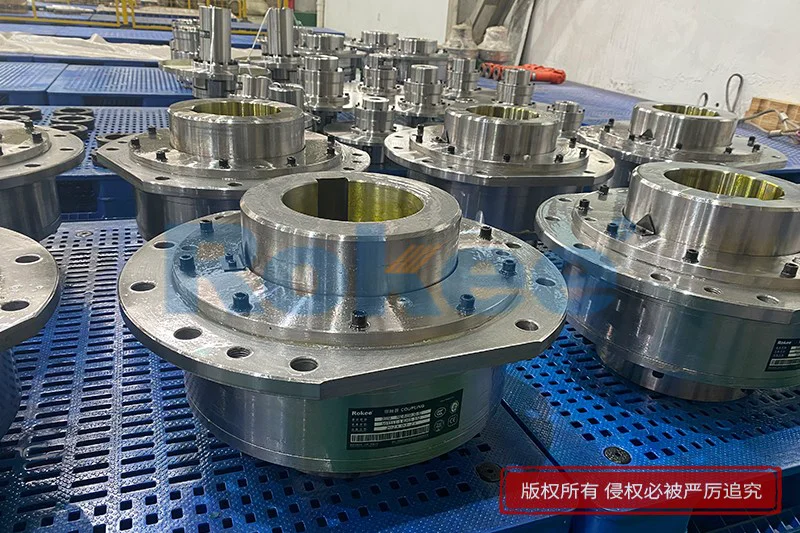
In industrial applications, barrel couplings are used in a wide range of machinery, including cranes, winches, conveyors, pumps, and motors. The design of the barrel coupling assembly drawing must be tailored to the specific application to ensure the coupling meets the unique requirements of that machinery. For example, couplings used in crane lifting mechanisms must be designed to withstand large radial loads and compensate for significant angular misalignments, while couplings used in pumps may need to be more compact and resistant to corrosion from fluids. The assembly drawing must reflect these application-specific requirements, with dimensions, materials, and tolerances chosen to ensure optimal performance in the intended environment.
The importance of a well-designed barrel coupling assembly drawing cannot be overstated. A precise, clear drawing ensures that the coupling is manufactured to the correct specifications, assembled properly, and maintained effectively, which in turn ensures the reliability and longevity of the machinery it is part of. Without a detailed assembly drawing, manufacturers may produce components that do not fit together, assembly technicians may make mistakes during installation, and maintenance workers may struggle to repair or replace worn parts. This can lead to increased downtime, higher maintenance costs, and even safety hazards in industrial settings.
In conclusion, a barrel coupling assembly drawing is a vital technical document that plays a critical role in the entire lifecycle of a barrel coupling, from design and manufacturing to assembly, inspection, and maintenance. It must be precise, clear, and comprehensive, providing all the necessary information to ensure the coupling functions as intended and meets the required performance standards. By carefully considering the design requirements, material selection, dimensional accuracy, assembly instructions, and inspection guidelines, engineers can create assembly drawings that facilitate the efficient production and reliable operation of barrel couplings in a wide range of industrial applications. The attention to detail in these drawings is essential for ensuring the safety, efficiency, and longevity of the machinery that relies on barrel couplings to transmit power and connect rotating shafts.
- Tags:
- Barrel Couplings ,
- sandwich panel line ,
- sandwich panel machine
- pu sandwich panel machine
« Barrel Coupling Assembly Drawing » Latest Update Date: May 9, 2026
https://www.rokeecoupling.net/blog/barrel-coupling-assembly-drawing.html