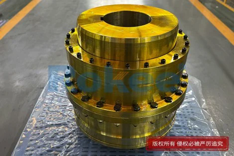
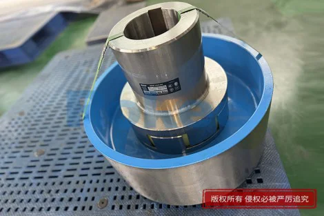
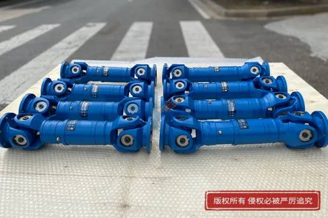
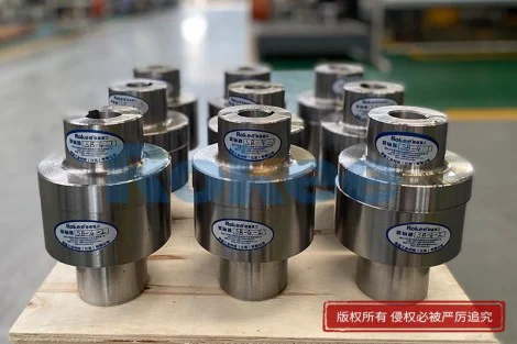
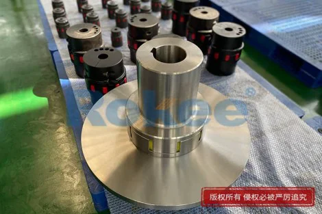
Large Gear Coupling
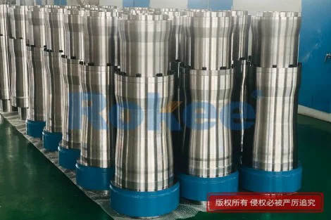
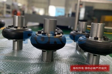
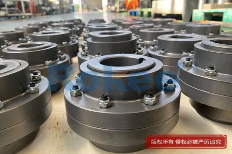
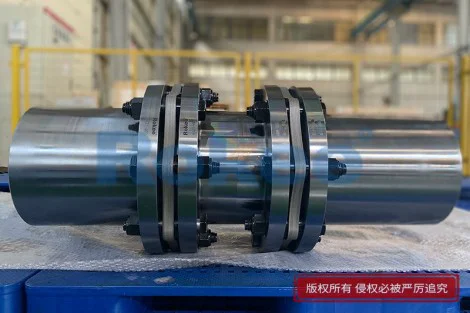
Rokee is a well-known Large Gear Coupling supplier from china, the page show cases of Large Gear Coupling, provide customized services based on user's drawings, and supporting exports.
Large gear couplings represent one of the most robust mechanical connection solutions for heavy-duty rotating equipment, designed to transmit high torque between two shafts while accommodating minor misalignment and thermal displacement during operation. At the core of the assembly lies a pair of hubs fitted with external gear teeth, which mesh internally with matching sleeve components. Unlike smaller flexible couplings that rely on elastomeric materials for deflection, the gear coupling achieves flexibility through the sliding contact between precision-machined gear profiles. This design choice makes it inherently suited for systems that must handle continuous heavy loads, frequent start-stop cycles, and dynamic torque fluctuations. Each gear tooth is shaped to distribute contact pressure evenly across the engagement surface, preventing localized wear that would quickly degrade weaker coupling types. Even under significant rotational forces, the meshed teeth maintain consistent power transfer without sudden loss of connection. Operators often select this coupling style for equipment where downtime carries severe operational consequences, as its fundamental mechanical structure delivers reliable performance over extended service intervals when properly maintained. It is important to recognize that the flexibility built into the gear geometry only compensates for limited radial, angular, and axial misalignment. Excessive offset between coupled shafts will amplify tooth friction, generate excess heat, and accelerate the rate of surface fatigue, which can lead to premature tooth chipping or complete coupling failure. For this reason, careful shaft alignment remains a critical step in installation, even though the coupling is engineered to tolerate small deviations from perfect alignment.
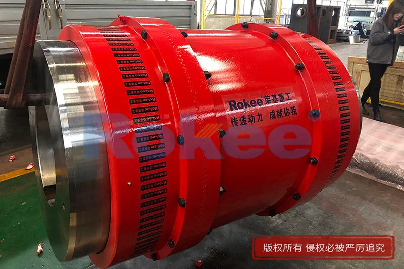
The manufacturing process for large gear couplings demands strict attention to material selection and precision machining, as the components must withstand repeated cyclic loading and surface contact stress over millions of rotation cycles. Base materials are chosen for high tensile strength, good hardening response, and resistance to contact fatigue. Raw forgings are typically used for the main hubs and sleeves, because forged structures have a uniform grain flow that improves toughness compared to cast alternatives. After rough machining, the gear teeth undergo surface hardening treatment to create a hard outer layer that resists abrasion and pitting, while the underlying core material retains ductility to absorb shock loads. Following heat treatment, finishing operations refine the tooth profile, tooth spacing, and surface roughness to ensure smooth meshing. Any irregularity in tooth geometry can create vibration spikes during rotation, which propagate through the connected machinery and damage bearings, seals, and other adjacent parts. Balancing is also performed on finished assemblies, especially for applications operating at elevated rotational speeds. Unbalanced rotating masses create centrifugal forces that increase bearing loads and amplify noise across the entire drive train. The finished components are inspected for dimensional accuracy, surface defects, and hardness consistency before assembly, to ensure every part meets the functional requirements of heavy power transmission.
Lubrication serves as the lifeline for large gear couplings, directly influencing service life, operating temperature, and noise levels during continuous operation. The meshing gear surfaces slide against one another as the coupling accommodates misalignment, and this sliding motion creates friction that must be controlled by a suitable lubricant. Without adequate lubrication, metal-to-metal contact occurs rapidly, leading to scoring, pitting, and eventual tooth breakdown. Grease is the most common lubricant choice for many large gear coupling installations, selected for its ability to stay within the enclosed coupling cavity and resist leakage. The lubricant forms a thin protective film between contacting tooth surfaces, reducing friction and dissipating some of the heat generated during sliding. Over time, contaminants such as dust, moisture, and metal wear particles accumulate within the lubricant. Moisture can trigger corrosion on gear surfaces, while solid particles act as abrasives that scratch and erode the tooth profile. Maintenance routines include periodic lubricant replenishment and full replacement, timed according to operating hours, load conditions, and ambient environment. Operating in high-temperature surroundings can degrade lubricant properties faster, shortening the service interval. Regular inspection of the lubricant condition helps operators catch early signs of internal wear before visible damage appears on the coupling components.
Understanding the types of misalignment that large gear couplings can manage helps engineers apply the coupling correctly and avoid preventable equipment damage. Angular misalignment arises when the centerlines of the two connected shafts intersect at a slight angle, rather than running perfectly parallel. Radial misalignment occurs when shaft centerlines remain parallel but are offset from one another. Axial displacement refers to the linear movement of shafts along their common axis, often caused by thermal expansion of equipment casings and shafts as operating temperatures rise. The curved profile of gear teeth allows limited sliding movement between the hub teeth and sleeve teeth to accommodate these three forms of displacement simultaneously. However, each form of misalignment adds friction between meshing teeth and increases heat generation. When misalignment exceeds the designed allowable range, the contact area of gear teeth becomes concentrated on narrow edges, creating high stress points. These stress points quickly develop fatigue cracks, which can spread and result in tooth breakage. It is also important to separate the capability of gear couplings from other flexible coupling types. Elastomeric couplings often handle greater misalignment but cannot match the torque capacity of large gear couplings. As a result, gear couplings remain the preferred option when high torque transmission is the primary requirement, and shaft alignment can be controlled within reasonable limits.
Vibration and noise characteristics are key performance indicators when evaluating large gear coupling operation in industrial drive systems. Minor vibration is normal during rotation, but abnormal vibration patterns signal underlying issues with the coupling or connected equipment. When gear teeth mesh unevenly, periodic force pulses transfer vibration to the supporting bearings and machine frames. Excessive vibration accelerates fatigue in not only the coupling itself but also nearby seals, fasteners, and foundation structures. Noise generated by a gear coupling mainly comes from tooth meshing impact, friction between sliding surfaces, and vibration transmitted through solid machine components. Well-installed, properly lubricated couplings produce a steady, low noise signature. A sudden increase in noise can indicate depleted lubricant, worsening misalignment, or developing tooth surface damage. Vibration monitoring techniques can track changes in vibration amplitude and frequency over time. Trending these readings allows maintenance teams to identify degradation at an early stage and schedule repairs during planned shutdown windows, rather than reacting to unplanned breakdown events. Changes in operating load also affect vibration behavior. Shock loads from sudden load spikes create transient vibration that stresses gear teeth and can initiate fatigue damage if repeated frequently.
Installation procedures for large gear couplings require careful planning and precise execution to maximize service life and avoid early failure. Before fitting the coupling components, the shaft journals and bore surfaces of hubs must be thoroughly cleaned to remove dirt, rust, and residual machining oils. Any surface contamination can prevent proper seating of the hub onto the shaft, leading to wobble and uneven load distribution. Hubs are mounted onto the respective shafts using appropriate fitting methods, ensuring tight contact between hub bore and shaft outer diameter. Once both hubs are secured, the sleeve assembly is fitted over the two sets of external gear teeth. Shaft alignment is then adjusted using measuring tools to minimize angular and radial offset. After alignment is finalized, fasteners for the sleeve assembly are tightened following a controlled sequence to maintain uniform clamping force. After initial startup, the system should run under light load for a period before applying full operating torque. This break-in period allows the lubricant to spread fully across all gear tooth surfaces and smooth any minor surface irregularities. Operators should monitor temperature and vibration closely during the initial run-in phase. Any rapid temperature rise or unusual vibration must be investigated immediately, as these signs point to alignment errors, insufficient lubrication, or improper assembly of coupling parts.
Operating environment significantly impacts the durability and maintenance needs of large gear couplings across different industrial applications. Ambient temperature affects both the mechanical properties of coupling components and the stability of the lubricant. In very hot environments, lubricants lose viscosity more quickly and oxidize at a higher rate, reducing their ability to form protective films. Cold ambient conditions can thicken lubricant, increasing startup torque and temporarily limiting the sliding movement between gear teeth. Exposure to moisture and humid air creates risk of corrosion on internal gear surfaces if the coupling sealing system becomes compromised. Dust, sand, and fine particulate matter present in many industrial settings can enter the coupling cavity through worn seals, contaminating lubricant and causing abrasive wear. Chemical vapors from nearby processing equipment may attack seal materials and degrade lubricant chemistry over time. Sealing designs are integrated into large gear couplings to block contaminants and retain lubricant within the sleeve enclosure. Seal components experience wear from rotation and temperature cycling, so periodic seal inspection and replacement form a core part of maintenance. Equipment located outdoors or in unconditioned plant spaces generally requires more frequent inspection than couplings housed inside clean, temperature-controlled machinery rooms.
Failure analysis of large gear couplings reveals recurring root causes that can be mitigated through better design, installation, and maintenance practices. One of the most common failure modes is surface pitting, which develops from repeated contact stress on gear tooth surfaces. Small fatigue cracks form below the surface, expand over many rotation cycles, and eventually detach small metal particles, leaving pits on the tooth face. Another common failure mode is tooth scoring, which occurs when lubrication breaks down, allowing direct metal contact and material transfer across meshing surfaces. Tooth breakage usually stems from extreme overload, excessive misalignment, or deep fatigue cracks that weaken the tooth cross-section. Fastener loosening can also occur when vibration is persistent, which may lead to sleeve displacement and complete separation of the coupling connection. Many failures do not happen instantly; they progress slowly through observable warning signs such as rising operating temperature, increased vibration, lubricant discoloration, or metal particles found in lubricant samples. Collecting and analyzing lubricant samples can detect tiny wear particles long before visible damage appears on the coupling. By understanding these typical failure pathways, engineering teams can set up targeted inspection schedules and operating limits to reduce the risk of catastrophic coupling failure during production runs.
Comparative assessment of large gear couplings against alternative power transmission devices highlights their unique strengths and inherent limitations. When compared to disc couplings, gear couplings deliver higher torque density within a similar physical envelope, meaning they can transmit greater torque without requiring a larger overall footprint. However, disc couplings rely on flexing metallic discs rather than sliding gear surfaces, so they do not require continuous lubrication. Chain couplings also offer high torque capacity, but they tend to generate more vibration and noise, and their performance degrades quickly when exposed to abrasive dust. Elastomeric couplings are quieter and tolerate larger misalignment, but their torque limits are much lower, and elastomer materials degrade when exposed to heat, oil, or certain chemicals. Large gear couplings excel where heavy torque must pass between shafts, and the design can support a sealed lubrication system. Their primary drawback is the ongoing lubrication requirement, which adds maintenance tasks and associated costs. Additionally, sliding contact between gear teeth creates inherent friction, so energy efficiency is slightly lower than some non-sliding coupling designs. This trade-off makes gear couplings the practical choice for heavy machinery, while other coupling types are more suitable for low-torque, high-precision, or low-maintenance priority systems.
Future developments in large gear coupling technology focus on material advances, optimized tooth geometry, improved sealing, and smarter condition monitoring to extend operating life and reduce maintenance burden. New alloy formulations and refined heat treatment techniques enhance resistance to contact fatigue and corrosion, allowing couplings to withstand higher loads and harsher environments. Computational modeling tools enable designers to refine gear tooth profiles to minimize sliding friction, reduce contact stress concentrations, and lower vibration excitation during meshing. Advanced sealing structures reduce the rate of lubricant loss and contaminant ingress, stretching intervals between lubricant service. Embedded sensing technologies are being integrated into some coupling assemblies to continuously track temperature, vibration, and in some cases lubricant quality. Real-time data feeds allow maintenance teams to shift from fixed-interval maintenance to condition-based maintenance, servicing equipment only when measurable indicators show degradation. Even with these technological improvements, the fundamental operating principle of meshing gear teeth remains unchanged. Proper shaft alignment, clean lubrication, and routine inspection will continue to be essential to reliable operation. As industrial systems push toward higher power density and longer uninterrupted operating cycles, large gear couplings will continue to evolve, maintaining their vital role as a dependable heavy-duty shaft connection solution for critical rotating equipment.
With excellent quality, we have been continuously providing many coupling products of various categories and uses complying with multiple standards and a full range of services, from the product selection to final installation and operation, for the industry fields of ferrous metallurgy, nuclear power, gas turbine, wind power, ropeway construction, lifting transportation, general equipment, etc.
pu sandwich panel line,pu sandwich panel machine,sandwich panel machine
« Large Gear Coupling » Latest Update Date: Oct 20, 2026
https://www.rokeecoupling.net/cases/large-gear-coupling.html