Split Bearing Type Large Universal Joint
Rokee is a well-known Split Bearing Type Large Universal Joint supplier from china, the page show cases of Split Bearing Type Large Universal Joint, provide customized services based on user's drawings, and supporting exports.
The split bearing type large universal joint represents a robust mechanical transmission component engineered to accommodate angular misalignment between two rotating shafts while transferring high torque across heavy-duty industrial applications. Unlike conventional universal joint designs that rely on integrated bearing assemblies enclosed within a solid housing, this construction separates the bearing structure into segmented parts, allowing for simplified assembly, inspection and maintenance without requiring full disassembly of the connected shaft system. At the core of the joint lies a cross spider connected to a set of split bearing units, each composed of two matching bearing shells that clamp around the trunnion surfaces of the spider. This split arrangement enables technicians to remove or replace individual bearing segments by undoing clamping fasteners, rather than sliding the entire joint away from the shaft ends, a key advantage in equipment layouts where shaft space is limited. The working principle follows the basic kinematics of universal joints: rotational motion from the driving shaft turns the cross spider, which then transmits rotation to the driven shaft even when the two shafts are not perfectly collinear. Minor variations in angular position during rotation create periodic speed fluctuations, a characteristic inherent to all single universal joints, and designers often pair two such joints in series to counteract this uneven motion. The split bearing configuration adds a layer of mechanical flexibility that is particularly valuable for large-scale systems, where solid, one-piece bearing caps become unwieldy to handle and install. Material selection for the split bearing shells prioritizes wear resistance and compressive strength, as these components continuously bear contact pressure from the rotating spider trunnions under heavy torque loads. Lubrication pathways are machined into the segmented bearing bodies, delivering lubricant to the contact surfaces to reduce friction, dissipate heat and slow the progression of surface wear over long operating cycles.
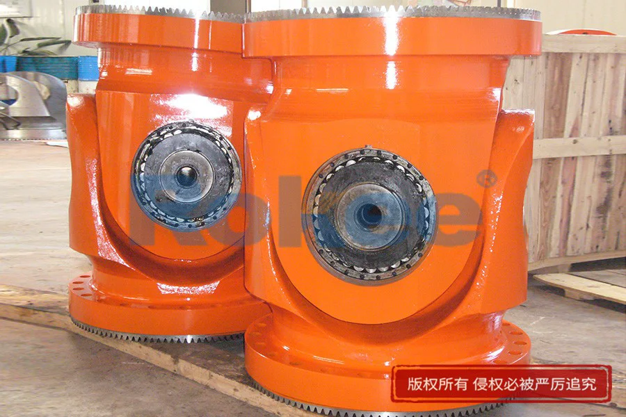
When evaluating load performance, the split bearing type large universal joint is tailored for heavy torque transmission scenarios where shock loading and transient load spikes are common during operation. The segmented bearing design distributes applied loads across multiple contact zones on the spider trunnion, lowering localized peak stress compared to some compact bearing constructions. Each split bearing half acts as an independent load-bearing element, secured tightly by bolted clamps to maintain consistent contact geometry under dynamic loading. Proper pre-tightening of the clamping fasteners is critical; insufficient clamping force can allow bearing segments to shift during rotation, leading to uneven wear, vibration and premature component failure, while excessive clamping may introduce unwanted residual stress that deforms the bearing shells and impairs free rotation. Operating angular deflection defines the usable working range of the joint. Within the allowable angular offset, the joint maintains stable torque transfer, but prolonged operation near the maximum deflection limit accelerates wear of both the split bearing surfaces and the spider trunnions. Dynamic loads generated by shaft misalignment produce cyclic forces that repeat with every rotation, creating fatigue stress on the bearing assembly. Engineers account for these cyclic loads during component sizing, ensuring the joint can endure millions of rotation cycles without developing cracks or surface spalling. The large form factor of this universal joint means the overall mass and inertia of the rotating assembly must be considered in system design. Higher rotational inertia requires greater starting torque to bring the shaft system up to operating speed, and sudden load changes can amplify vibration. Balancing of the assembled joint reduces vibration at operating speeds, protecting adjacent shaft supports and connected machinery from unnecessary dynamic stress. Continuous monitoring of operating temperature is also important, as elevated temperature signals insufficient lubrication, excessive friction or misalignment issues within the split bearing interface.
Installation procedures for the split bearing type large universal joint differ significantly from standard solid bearing universal joints, mainly because the bearing units can be mounted after positioning the cross spider between the two yoke assemblies. The process begins with aligning the driving and driven shaft yokes to hold the cross spider in place, before fitting each pair of split bearing shells around the spider trunnions. The two halves of each bearing are brought together and secured using clamping hardware, with care taken to avoid pinching or displacing the internal lubrication seals. Sealing elements fitted at the edge of each split bearing prevent contamination from dust, moisture and abrasive particles present in the surrounding operating environment, while also retaining lubricant inside the bearing cavity. During installation, technicians verify that the cross spider can pivot freely within the assembled bearings. Binding or stiff movement indicates misaligned bearing halves, over-tightened clamps or debris trapped between the contact surfaces. After completing bearing assembly, shaft alignment is adjusted to set the working angle of the joint to the designed value. Even with the universal joint’s ability to tolerate angular offset, excessive parallel misalignment between shafts creates extra bending loads that the split bearing assembly is not designed to absorb. Once fully assembled, a manual rotation check confirms smooth motion before the equipment is placed under power. The ability to install bearings in segmented form is especially beneficial in confined spaces where removing the entire universal joint from the shaft line would require dismantling large surrounding machine structures. This feature cuts down installation time and reduces the risk of damaging other transmission parts during assembly work. Following installation, an initial short run-in period allows the mating surfaces of the split bearings to settle into uniform contact, after which a recheck of fastener tension is recommended to account for minor seating shifts.
Maintenance stands as one of the most prominent benefits of the split bearing type large universal joint, as the segmented bearing architecture supports targeted component replacement instead of full joint replacement when wear occurs. During routine maintenance inspections, operators can access the split bearing assemblies without removing the cross spider or disconnecting the complete shaft connection. Visual inspection checks for seal damage, lubricant leakage, surface scoring on bearing shells and trunnion wear. Vibration and temperature readings provide additional indicators of bearing health. When wear exceeds acceptable limits, individual split bearing units can be disassembled by loosening the clamping bolts and separating the two bearing halves. The worn bearing segments are extracted and replaced with new matching parts, while the original cross spider can often remain in service if its trunnion surfaces are still sound. This targeted maintenance approach reduces material waste and cuts downtime, a meaningful advantage for equipment that operates continuously and cannot tolerate extended shutdown periods. Lubrication maintenance follows a scheduled cycle, with fresh lubricant injected through the built-in passages to flush out degraded lubricant and wear debris. The frequency of lubrication service depends on operating speed, load magnitude, ambient temperature and environmental conditions. In dirty environments, seal integrity becomes a primary maintenance concern; damaged seals quickly allow abrasive contaminants into the bearing contact zone, causing rapid abrasive wear. Maintenance protocols also include periodic re-torqueing of bearing clamp fasteners, as vibration over time can loosen bolt tension. Records of bearing replacement, lubrication events and fastener checks help track component service life and identify trends that signal deteriorating operating conditions before catastrophic failure takes place.
The kinematic characteristics of the split bearing type large universal joint determine its motion behavior and influence how it integrates into complete rotating transmission systems. A single universal joint of this design produces fluctuating output rotational speed when operated under angular misalignment. As the driving yoke rotates at constant speed, the driven yoke speeds up and slows down twice per full rotation. This cyclic speed variation creates torsional vibration in the downstream shafting, which can induce shock loads on bearings, gears and other connected equipment components. To mitigate this kinematic effect, system designers commonly deploy two universal joints in sequence. When arranged correctly, the speed fluctuations produced by the first joint cancel out those generated by the second joint, delivering near-constant rotational speed to the final driven component. The split bearing structure does not alter this fundamental kinematic behavior of universal joints, but its mechanical stiffness affects how the joint responds to torsional oscillations. The clamped split bearing assembly maintains consistent clearances between the spider trunnion and bearing shells, preserving predictable motion geometry even under heavy torque. Clearance control is essential: excessive internal clearance allows unwanted play during direction reversals, which creates impact loads every time torque direction switches. Too little clearance restricts the free pivoting movement of the cross spider, raising friction and heat generation. During dynamic operation, the cross spider continuously pivots inside the split bearings to accommodate the fixed working angle between shafts. This sliding and rolling contact at the trunnion and bearing interface generates friction that must be managed by lubrication. Understanding these kinematic traits allows engineers to properly select the number of joints, set working angles and design supporting shaft structures that minimize vibration and torsional stress across the whole transmission system.
Material choices for the split bearing type large universal joint are carefully selected to balance strength, wear resistance, impact tolerance and machinability for heavy-duty use. The cross spider is typically produced from high-strength forged material, which can withstand repeated torsional and bending loads from torque transmission and shock events. Forged structures offer uniform internal grain flow, improving resistance to fatigue crack initiation under cyclic loading. The split bearing shells are often made from materials engineered for low friction and high compressive resistance. Some bearing shells feature surface treatments that enhance wear performance, creating a hardened contact layer that resists scoring and abrasion while maintaining a tough substrate to avoid brittle fracture under impact. Clamping fasteners are manufactured from high-tensile strength material to sustain consistent preload across wide temperature ranges and vibratory operating conditions. Sealing components are formulated to resist degradation from lubricants, heat and environmental chemicals, retaining flexibility over long service periods. Material selection also considers thermal expansion differences between the spider and split bearing components. As operating temperature rises, each material expands at a unique rate, which changes the internal clearance of the bearing assembly. If mismatched material expansion characteristics are not accounted for, bearings may bind when hot or develop excessive clearance at low temperatures. Surface finishing on trunnions and the inner surfaces of split bearing shells reduces initial friction and limits the rate of wear. Rough surface imperfections act as stress concentration points and can tear lubricant films, leading to metal-to-metal contact. Each material combination is evaluated against the expected operating environment, including exposure to moisture, airborne grit and temperature extremes, to ensure long-term reliability of the joint assembly.
Operational limitations of the split bearing type large universal joint must be understood to prevent misuse and premature component damage. While the joint accommodates angular misalignment, it cannot compensate for large parallel shaft offset. Parallel displacement between shafts imposes bending loads on the cross spider and split bearing assemblies, loads that these components are not designed to withstand. Over time, repeated bending stress leads to spider fracture and accelerated bearing failure. Operating speed is another boundary constraint. At excessively high rotational speeds, centrifugal forces act on the split bearing assembly and cross spider, increasing contact pressure and raising operating temperature. High speed also amplifies vibration, which can loosen bearing clamp fasteners and degrade seal performance. Heavy shock loads beyond the designed torque capacity cause plastic deformation of trunnion surfaces or cracking in the split bearing shells. Even short-duration overload events can create permanent damage that may not be visible during routine visual checks. The working angular range has upper limits as well. When operated at angles beyond the rated value, sliding motion at the bearing contact surfaces increases dramatically, boosting friction and heat generation and shortening bearing service life. Environmental factors also impose practical limits. Operations in heavily abrasive surroundings accelerate seal wear and contaminate lubricant, requiring more frequent inspection and service. Extreme cold can stiffen sealing materials and thicken lubricant, increasing starting friction. System designers must match the joint’s capabilities to the actual operating profile, including peak torque, continuous torque, rotation speed, shaft misalignment and environmental conditions. Operating outside these defined limits reduces service life and raises the risk of unplanned machine downtime.
Vibration and noise management form an important aspect of deploying split bearing type large universal joints within rotating machinery systems. Several sources generate vibration during operation, including the inherent speed fluctuation of single universal joints, residual imbalance of rotating components, internal bearing clearance and shaft misalignment. Vibration propagates through the shafting into supporting bearing housings and machine frames. Over time, sustained vibration loosens bolted connections elsewhere in the equipment and can induce fatigue damage in structural parts. Proper dynamic balancing of the universal joint assembly reduces vibration caused by uneven mass distribution around the rotation axis. Maintaining consistent preload on split bearing clamps prevents relative movement between bearing halves, which would otherwise produce impact noise and vibration during torque reversals. Internal bearing clearance requires careful control. Small amounts of clearance allow lubricant to flow and accommodate thermal expansion, but excessive clearance creates hammering noise and shock loads every time torque direction changes. Lubrication quality directly influences noise levels. A full, intact lubricant film dampens contact noise between trunnions and bearing shells, while insufficient lubrication leads to metal contact and harsh, high-frequency noise. Operators often use vibration measurement tools to track vibration signatures over time. Rising vibration amplitude acts as an early warning sign of developing faults such as bearing wear, loose clamps or seal failure. Noise produced by the joint can also serve as a simple diagnostic cue, though noise alone cannot quantify the severity of internal wear. By controlling alignment, balancing, lubrication and fastener tension, system builders can keep vibration and noise within acceptable levels, protecting the integrity of the entire mechanical transmission setup.
Comparisons between split bearing type large universal joints and conventional solid bearing universal joints highlight distinct tradeoffs in serviceability, mechanical complexity and dimensional requirements. Solid bearing universal joints feature one-piece bearing cups pressed or bolted into the yoke bores. To replace bearings on this traditional design, the universal joint must be fully separated from the shafting, requiring space to slide the yokes off the shaft ends. This can be impractical in tightly arranged machinery layouts. The split bearing design removes this constraint by enabling bearing service in place, which is its most decisive advantage. However, the split construction introduces additional sealing interfaces along the split line of each bearing shell. These mating seams represent potential leak points that require precise machining and properly fitted seals to maintain lubricant retention and block contaminant ingress. Solid bearing units have fewer sealing interfaces and can sometimes offer simpler sealing arrangements. In terms of manufacturing, split bearing shells demand tighter dimensional control for the mating split faces to ensure the two halves align perfectly when clamped. Poor matching of split surfaces leads to uneven bearing contact and accelerated wear. Solid bearing cups do not have this split interface requirement, simplifying some production stages. Load carrying capacity can be comparable when both designs are sized for the same torque rating, but the split bearing version’s performance depends heavily on reliable clamping force. Loss of clamp tension quickly degrades performance, whereas solid pressed bearing assemblies do not rely on ongoing bolt preload to maintain bearing position. The split bearing configuration tends to have slightly more components in the bearing assembly, which increases the number of parts to inspect during maintenance. For applications where equipment access is restricted and downtime costs are high, the improved serviceability of the split bearing large universal joint outweighs its added sealing and clamping complexity.
Future development directions for split bearing type large universal joints focus on enhancing wear performance, reducing maintenance demand and expanding the usable operating range for heavy transmission systems. Advancements in surface modification techniques can improve the friction and wear characteristics of split bearing inner surfaces and spider trunnions, lowering wear rates and extending service intervals. New sealing configurations aim to improve resistance against fine abrasive particles, extending seal life in harsh operating environments and reducing the frequency of lubricant contamination. Improvements in fastener technology and clamping geometry help maintain stable preload over longer periods, resisting loosening under continuous vibration and thermal cycling. Integrated sensing elements may be incorporated into future designs to monitor bearing temperature, vibration or lubricant condition in real time, allowing condition-based maintenance instead of fixed scheduled service. This shift toward condition monitoring can eliminate unnecessary maintenance work and identify developing faults at an earlier stage. Design refinements also seek to reduce friction losses within the split bearing assembly, improving overall mechanical efficiency of the transmission system and lowering heat generation during continuous operation. Engineers continue to explore optimized bearing contact profiles that distribute pressure more evenly across the bearing surface, further reducing localized stress. These evolutionary improvements preserve the core advantage of the split bearing architecture: convenient, in-place bearing maintenance for large high-torque universal joints. As heavy industrial systems demand greater reliability and longer uninterrupted operation, the split bearing type large universal joint will continue to evolve as a practical solution for power transmission across misaligned rotating shafts, balancing robust load capacity with accessible serviceability for demanding heavy-duty applications.
With excellent quality, we have been continuously providing many coupling products of various categories and uses complying with multiple standards and a full range of services, from the product selection to final installation and operation, for the industry fields of ferrous metallurgy, nuclear power, gas turbine, wind power, ropeway construction, lifting transportation, general equipment, etc.
pu sandwich panel line,pu sandwich panel machine,sandwich panel machine
« Split Bearing Type Large Universal Joint » Latest Update Date: Oct 20, 2026
https://www.rokeecoupling.net/cases/split-bearing-type-large-universal-joint.html


