In the intricate ecosystem of mechanical transmission systems, the rational connection between rotating shafts determines the operational stability, power transmission efficiency and service life of the entire mechanical equipment. As a classic and reliable transmission connecting component, cross joint coupling has become an indispensable core part in various mechanical structures by virtue of its unique spatial motion adaptation capability and stable torque transmission performance. This mechanical component breaks through the transmission limitations of traditional rigid connecting structures, and can maintain continuous and effective power transmission under the conditions of shaft angle deviation, spatial staggered arrangement and relative displacement, providing a solid guarantee for the flexible operation of complex mechanical equipment. With the continuous upgrading of industrial manufacturing technology and the diversification of mechanical operation scenarios, the structural design and application scope of cross joint coupling have been continuously optimized, and its inherent mechanical advantages make it widely used in heavy industry machinery, transportation equipment, automated production lines and many other industrial fields.
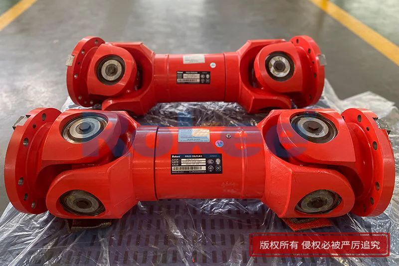
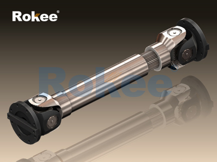
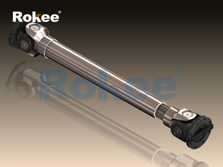
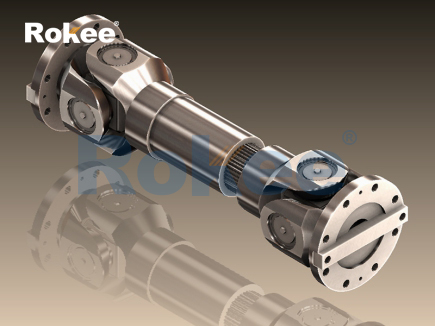
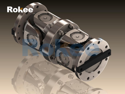
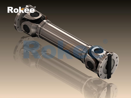
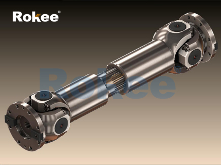
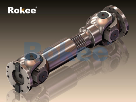
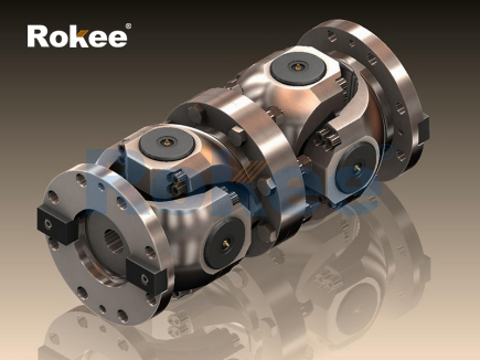
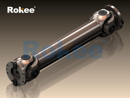
The basic structural composition of cross joint coupling follows simple and rigorous mechanical design logic, and each component has clear functional division and mutual coordination to complete the torque transmission task. The core component of this coupling is the cross-shaped intermediate connector, which is equipped with symmetrical pin shafts that can realize flexible rotational deflection in multiple directions. The two ends of the cross structure are connected with the fork-shaped connectors fixed on the driving shaft and the driven shaft respectively, forming a mutually hinged movable connection structure. This special assembly mode enables the driving shaft and the driven shaft to form a certain angular offset in the spatial position without losing the transmission connection relationship. In the single-section cross joint coupling structure, a single cross connection unit is used to realize the angle compensation between two shafts, which is suitable for mechanical occasions with small shaft deflection angle and stable operation load. For working conditions with larger spatial offset and higher transmission stability requirements, the double-section cross joint coupling composed of two cross connection units and intermediate connecting shafts is usually adopted. The tandem structure of double sections can effectively balance the instantaneous speed fluctuation generated during the operation of single-section coupling, further optimize the spatial displacement compensation ability, and adapt to more complex shaft position layout environments.
The working principle of cross joint coupling is derived from the spatial hinge motion mechanism, and the torque transmission process contains unique kinematic characteristics. When the driving shaft rotates at a constant speed, the cross connector swings around the pin shaft along with the rotation angle of the driving fork, and transmits the rotational torque to the driven fork and the driven shaft through mechanical contact force. In this motion system, the existence of shaft angle deviation will lead to periodic changes in the instantaneous angular velocity of the driven shaft, which is the inherent kinematic characteristic of single-section cross joint coupling. The velocity fluctuation amplitude is positively correlated with the offset angle between the two shafts. The larger the angle, the more obvious the instantaneous velocity change. This periodic motion characteristic will produce slight mechanical vibration and alternating load during high-speed operation. Therefore, in practical industrial applications, designers often use double-section structural configuration to offset velocity fluctuations. By reasonably adjusting the installation angle of the two cross joints, the velocity deviation generated by the front joint can be completely counteracted by the rear joint, so that the driven shaft can maintain a stable constant-speed rotation state, realizing efficient and smooth power transmission.
Material selection and processing technology are the key factors affecting the mechanical performance and service life of cross joint coupling. Most of the mainstream cross joint coupling components are made of high-strength alloy materials, which have excellent mechanical properties such as high tensile strength, good toughness and strong fatigue resistance. The cross shaft and pin shaft, as the force-bearing core parts, usually undergo precise heat treatment processes to improve surface hardness and wear resistance, so as to resist the friction loss and contact fatigue damage caused by long-term meshing motion. The fork-shaped connecting parts need to bear large shear force and tensile force during operation, so the materials are required to have good structural rigidity and impact resistance. In some light-load and low-speed application scenarios, partial auxiliary components can be made of high-performance engineering polymers. These polymer materials have natural self-lubricating characteristics, which can reduce the friction coefficient between moving parts, weaken operation noise, and avoid the corrosion problem of metal materials in humid environments. The optimized combination of different materials enables cross joint coupling to take into account the dual requirements of structural strength and environmental adaptability, and meet the operating standards of various working conditions.
Compared with other types of coupling products in the mechanical market, cross joint coupling has prominent comprehensive performance advantages. Different from rigid couplings that require extremely high coaxiality of shafts and have no displacement compensation capability, cross joint coupling can actively adapt to angular displacement, radial displacement and axial displacement between shafts, and has excellent spatial error tolerance. This characteristic greatly reduces the assembly accuracy requirements of mechanical equipment, lowers the difficulty of equipment installation and debugging, and saves the time cost of mechanical assembly. In terms of load bearing, this coupling can withstand large instantaneous impact load and alternating load, and will not produce structural fracture or permanent deformation under severe working conditions such as sudden torque surge. Its internal movable hinge structure can absorb part of the vibration energy generated during mechanical operation, reduce the vibration conduction between shafts, and protect bearings, gears and other precision transmission components from impact damage. In addition, the overall structure of cross joint coupling is compact, the number of parts is small, and the disassembly and assembly process is simple, which brings great convenience for daily maintenance and component replacement of mechanical equipment.
In actual industrial operation scenarios, cross joint coupling also has certain application limitations, which need to be reasonably avoided through scientific selection and standardized installation. The most obvious limitation comes from the inherent velocity fluctuation of single-section structure. When the shaft offset angle is too large and the rotation speed is too high, the periodic velocity change will produce obvious centrifugal force and mechanical vibration, which will increase the abrasion loss of parts and even affect the running stability of the whole equipment. Meanwhile, the friction between the cross shaft and the fork contact surface will generate continuous heat energy during long-term operation. If the heat cannot be dissipated in time, it will accelerate the aging of lubricating medium and reduce the surface hardness of metal parts. In addition, although the structural strength of cross joint coupling is excellent, long-term operation under extreme overload conditions will still cause irreversible wear of the hinge contact surface, resulting in increased transmission clearance and reduced motion accuracy. In view of these limitations, mechanical designers need to comprehensively consider factors such as shaft offset angle, operating speed, load magnitude and working environment, and select single-section or double-section structural forms in a targeted manner, and match reasonable lubrication and heat dissipation schemes.
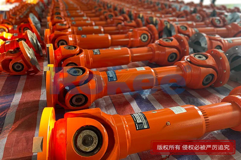
The industrial application coverage of cross joint coupling involves multiple important industrial sectors, and it shows unique application value in different mechanical equipment. In the field of transportation machinery, this coupling is applied to the power transmission structure of mobile transportation equipment. It can adapt to the vibration displacement and angle change generated during the driving process of equipment, and stably transmit the power output by the power unit to the walking execution structure, ensuring the flexibility and reliability of equipment operation. In heavy industrial machinery such as rolling mills and mining machinery, cross joint coupling undertakes the transmission task of high torque. Its high-strength structural characteristics can cope with the harsh working conditions of heavy load, dust and impact, and maintain stable power output for a long time. In automated production equipment, many mechanical arms and transmission mechanisms need to complete multi-angle spatial rotation actions. The flexible hinge performance of cross joint coupling can meet the requirements of multi-directional motion transmission, realizing the accurate transmission of power in complex motion trajectories. In addition, in agricultural machinery, engineering construction machinery and other equipment working in complex outdoor environments, the good environmental adaptability of cross joint coupling also enables it to maintain stable working performance under harsh conditions such as mud, humidity and low temperature.
Daily maintenance and scientific maintenance are important means to extend the service life of cross joint coupling and maintain stable transmission performance. Lubrication management is the core link of maintenance work. High-quality lubricating medium can form a uniform protective film on the friction contact surface between the cross shaft and the fork, reducing direct metal friction, lowering wear rate and operation noise, and taking away the heat generated by friction to realize auxiliary heat dissipation. It is necessary to regularly check the sealing performance of the coupling structure to prevent external dust, impurities and corrosive media from entering the movable hinge gap, so as to avoid abrasive wear and chemical corrosion of internal parts. During the regular inspection of equipment, staff need to observe the rotation flexibility of the coupling, check whether there is abnormal vibration and noise during operation, and judge whether the internal parts have excessive wear or loose assembly. For the coupling that has been used for a long time, the aging lubricating medium should be replaced regularly, and the severely worn pins and connecting forks should be updated in a timely manner to eliminate potential safety hazards such as transmission failure caused by component aging.
With the continuous progress of industrial mechanical technology, the optimization and upgrading of cross joint coupling is also advancing in the direction of high precision, high durability and lightweight. In terms of material optimization, new composite alloy materials and surface strengthening treatment processes are gradually applied to the production of couplings. These new technologies can further improve the wear resistance, corrosion resistance and fatigue resistance of components, and adapt to higher standard industrial working conditions. In terms of structural design, the internal hinge gap and contact angle are optimized through simulation calculation to reduce mechanical friction loss and velocity fluctuation amplitude, improving transmission efficiency and operation stability. In terms of processing technology, high-precision CNC machining technology is used to control the dimensional tolerance of each component, so that the assembly matching degree of parts is higher, and the transmission clearance is reduced. In addition, combined with the intelligent monitoring technology of mechanical equipment, some optimized cross joint couplings are equipped with auxiliary monitoring structures, which can feed back the operating temperature, vibration amplitude and wear degree of components in real time, providing data support for intelligent maintenance of equipment.
From the perspective of mechanical transmission development, cross joint coupling, as a mature and basic transmission component, will still occupy an irreplaceable important position in the future industrial system. Its core advantages of simple structure, strong adaptability and low maintenance cost make it difficult to be completely replaced by emerging coupling products in a short time. In the future industrial development trend of intelligent manufacturing and flexible production, the diversified motion adaptation capability of cross joint coupling can well match the flexible operation requirements of automated production lines and intelligent mechanical equipment. With the continuous improvement of energy-saving and consumption-reducing requirements of mechanical equipment, the optimized cross joint coupling will further reduce friction energy consumption, improve power transmission efficiency, and contribute to the energy-saving operation of industrial equipment. At the same time, with the expansion of application scenarios such as special environment operation equipment and extreme condition testing machinery, the environmental adaptation performance of cross joint coupling will be further optimized to meet the transmission needs of more complex working conditions.
In conclusion, cross joint coupling integrates simple mechanical structure, unique kinematic characteristics and excellent comprehensive performance, and solves many difficult problems in shaft connection and power transmission in mechanical systems. Its displacement compensation capability, impact resistance and stable torque transmission performance make it widely used in various industrial machinery. Although restricted by inherent kinematic characteristics and material properties, it has certain limitations in high-speed and ultra-high-precision working conditions, and its application scope can be effectively expanded through structural optimization and scientific type selection. With the continuous innovation of material technology and processing technology, the comprehensive performance of cross joint coupling will be continuously improved. Relying on its reliable mechanical performance and high application cost performance, this classic mechanical component will continue to provide stable transmission support for the development of modern manufacturing industry, and play an important role in promoting the iterative upgrading and efficient operation of mechanical equipment in various industries.
pu sandwich panel line,pu sandwich panel machine,sandwich panel machine
« Cross Joint Couplings » Latest Update Date: May 9, 2026
https://www.rokeecoupling.net/tags/cross-joint-couplings.html