Barrel coupling design is a critical aspect of mechanical engineering that focuses on creating reliable, efficient connections between rotating shafts in various industrial applications. These couplings serve as essential components in transmitting torque while accommodating misalignments, absorbing shocks, and ensuring smooth operation of machinery. Unlike other types of couplings, barrel couplings are specifically engineered to handle high radial loads and significant torque transmission, making them indispensable in heavy-duty equipment such as cranes, hoists, conveyor systems, and industrial machinery. The design process of barrel couplings involves a comprehensive understanding of mechanical principles, material properties, and application requirements, as each component and dimension must be carefully calibrated to meet the demands of the specific operating environment.

At the core of barrel coupling design is the need to balance functionality, durability, and performance. A well-designed barrel coupling must effectively transmit torque from one shaft to another without excessive wear or energy loss, while also compensating for inevitable misalignments that occur during operation. Shaft misalignment can arise from various factors, including installation errors, thermal expansion, structural deflection under load, and wear of bearings over time. Barrel couplings address this challenge through their unique structural design, which typically includes a sleeve, hub, and a series of cylindrical barrels or rollers that allow for angular and axial displacement. This design feature not only protects the connected shafts and bearings from excessive stress but also extends the overall service life of the machinery.
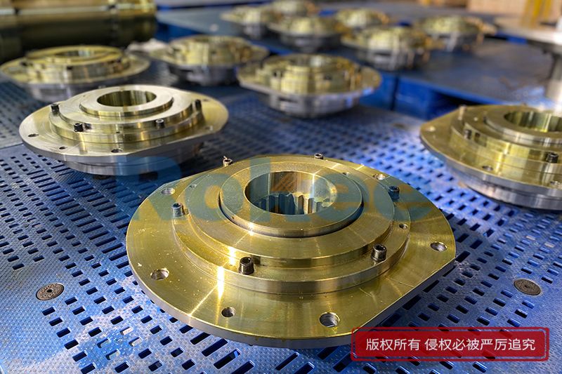
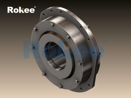
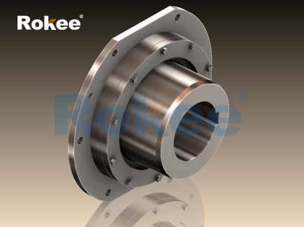
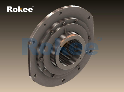
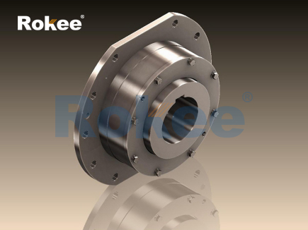
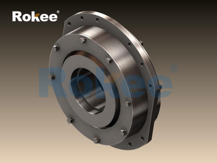
The structural composition of a barrel coupling is a key determinant of its performance and suitability for specific applications. Most barrel couplings consist of two main components: a hub that attaches to the drive shaft and a sleeve that connects to the driven shaft, with a series of hardened steel barrels positioned between them. The barrels are typically housed in semi-circular cogs or grooves on both the hub and sleeve, creating a contact surface that facilitates torque transmission. The design of these cogs and the arrangement of the barrels are critical, as they directly influence the coupling’s ability to transmit torque, absorb radial loads, and compensate for misalignments. In some designs, the barrels are guided axially by spring lock washers, which ensure that the barrels remain in the correct position during operation and prevent excessive wear. Additionally, sealing elements such as fluororubber skeleton oil seals or labyrinth seals are often integrated into the design to protect the internal components from contamination by dust, moisture, and other foreign particles, which can degrade performance and shorten service life.
Material selection is another fundamental aspect of barrel coupling design, as the materials used must possess the necessary strength, durability, and resistance to wear and corrosion to withstand the harsh conditions of industrial operation. The choice of material depends on several factors, including the magnitude of the torque and radial load, the operating temperature, the presence of corrosive substances, and the expected service life of the coupling. High-strength alloy steels are commonly used for the hub, sleeve, and barrels due to their excellent tensile strength, hardness, and resistance to fatigue. These steels are often heat-treated through processes such as quenching and tempering to enhance their mechanical properties, ensuring that they can withstand the high stresses generated during torque transmission. In applications where corrosion resistance is a concern, materials such as stainless steel or alloy steels with corrosion-resistant coatings may be used to prevent rust and degradation. The barrels, which are critical for torque transmission and load absorption, are typically made of hardened steel with a high wear resistance, as they are subjected to constant contact and friction during operation.
The design process of barrel couplings also involves careful consideration of torque transmission capacity, which is determined by the size and number of barrels, the material properties, and the contact area between the barrels and the cogs. Torque is transmitted through the contact between the barrels and the inclined surfaces of the cogs, with the force distributed evenly across the barrels to minimize stress concentration. The maximum torque that a barrel coupling can transmit is directly related to the diameter of the barrels, the number of barrels, and the material’s shear strength. Engineers must calculate the required torque capacity based on the application’s needs, ensuring that the coupling can handle both the nominal torque and any peak torques that may occur during start-up or overload conditions. Additionally, the design must account for radial loads, which are common in applications such as cranes and hoists where the coupling supports the weight of the drum or other rotating components. The barrel coupling’s structure must be robust enough to absorb these radial loads without excessive deflection or deformation, which could lead to misalignment and premature failure.
Misalignment compensation is a key design feature of barrel couplings, as even small amounts of misalignment can cause significant stress on shafts, bearings, and other components. Barrel couplings are designed to accommodate both angular and axial misalignments, with the degree of compensation depending on the specific design. Angular misalignment is compensated by the ability of the barrels to roll within the cogs, allowing the hub and sleeve to rotate at a slight angle relative to each other. The maximum angular misalignment that a barrel coupling can accommodate typically ranges from ±1° to ±3°, depending on the design and size of the coupling. Axial misalignment, which occurs when the shafts move along their axial direction, is absorbed by the axial movement of the barrels within the cogs. The maximum axial displacement that can be accommodated varies by coupling size, ranging from ±3 mm to ±8 mm or more. This ability to compensate for misalignments is crucial in industrial applications, as it reduces the risk of bearing failure, shaft bending, and other mechanical issues that can lead to costly downtime.
Another important consideration in barrel coupling design is the ease of assembly and maintenance. Industrial machinery often requires regular maintenance to ensure optimal performance, and couplings that are difficult to assemble or disassemble can increase maintenance time and costs. Barrel couplings are typically designed with a compact structure that allows for easy installation, with many models featuring an integrated inner ring that simplifies the assembly process. Additionally, some designs include wear indicators on the outer cover, which allow operators to monitor the condition of the coupling without disassembling it. This feature is particularly useful in applications where downtime is costly, as it enables proactive maintenance and prevents unexpected failures. The ability to re-grease the coupling without removing the sealing elements is another design feature that enhances maintainability, as it allows for regular lubrication to reduce friction and wear.
Finite element analysis (FEA) has become an essential tool in barrel coupling design, allowing engineers to simulate the performance of the coupling under various operating conditions and optimize its design. FEA involves creating a 3D model of the coupling and applying loads that simulate real-world operating conditions, such as torque, radial load, and misalignment. The analysis provides detailed information about stress distribution, deflection, and fatigue life, allowing engineers to identify potential weak points in the design and make necessary adjustments. For example, FEA can be used to optimize the shape of the cogs, the size and arrangement of the barrels, and the thickness of the hub and sleeve to ensure that the coupling can withstand the required loads without excessive stress. This approach not only improves the performance and durability of the coupling but also reduces the need for physical prototyping, saving time and costs in the design process.
The application of barrel couplings spans a wide range of industrial sectors, each with unique requirements that influence the design process. In crane and hoist applications, for example, barrel couplings are used to connect the gearbox output shaft to the wire rope drum, transmitting high torques and absorbing radial loads while compensating for misalignments caused by structural deflection. In these applications, the coupling must be designed to handle frequent start-stop cycles and heavy-load impacts, requiring a robust structure and high fatigue resistance. In conveyor systems, barrel couplings are used to connect the motor to the conveyor drum, ensuring smooth power transmission and accommodating misalignments caused by thermal expansion or belt tension. In nuclear power, gas turbine, and wind power applications, barrel couplings must meet strict performance standards, as failure can have serious consequences. These applications often require couplings with high torque capacity, corrosion resistance, and long service life, leading to the use of advanced materials and optimized designs.
Design optimization of barrel couplings also involves addressing potential failure modes, such as wear, fatigue, and corrosion. Wear of the barrels and cogs is a common failure mode, caused by constant friction during operation. To mitigate this, engineers may use materials with high wear resistance, apply surface treatments such as hardening or coating, and ensure proper lubrication. Fatigue failure can occur due to repeated stress cycles, particularly in applications with frequent start-stop operations or variable loads. To prevent fatigue, the design must avoid stress concentrations, and the materials must have sufficient fatigue strength. Corrosion failure is a concern in harsh environments, such as those with high humidity, chemicals, or saltwater. In these cases, corrosion-resistant materials or protective coatings are used to extend the service life of the coupling.
Lubrication is a critical aspect of barrel coupling design, as it reduces friction between the moving components, minimizes wear, and dissipates heat. The type of lubricant used depends on the operating temperature, load, and speed of the coupling. Grease is commonly used in barrel couplings due to its ability to stay in place and provide long-lasting lubrication. The lubricant must be compatible with the materials used in the coupling and must be able to withstand the operating conditions, such as high temperatures or exposure to contaminants. Regular lubrication is essential to maintain the performance of the coupling, and some designs include features that allow for easy re-greasing without disassembling the coupling. Proper lubrication not only extends the service life of the coupling but also improves its efficiency by reducing energy loss due to friction.
In recent years, advancements in materials science and manufacturing technology have led to improvements in barrel coupling design. The use of high-strength, lightweight materials has allowed for the development of more compact and efficient couplings, while advanced manufacturing processes such as precision machining and 3D printing have enabled more complex designs with tighter tolerances. Additionally, the integration of intelligent monitoring systems, such as vibration sensors and temperature probes, has allowed for real-time monitoring of the coupling’s performance, enabling proactive maintenance and reducing the risk of unexpected failures. These advancements have expanded the range of applications for barrel couplings and improved their reliability and efficiency.
When designing a barrel coupling, engineers must also consider the overall system dynamics, including the interaction between the coupling and other components such as shafts, bearings, and gearboxes. The coupling must be compatible with the size and speed of the shafts, and its design must not introduce excessive vibration or noise. Vibration can be caused by imbalances in the coupling or misalignments, and it can lead to premature failure of the coupling and other components. To minimize vibration, the coupling must be balanced during the manufacturing process, and its design must ensure that the center of mass is aligned with the axis of rotation. Additionally, the coupling’s torsional stiffness must be matched to the system’s requirements to avoid resonance, which can cause severe vibration and damage to the machinery.
The design process of a barrel coupling is iterative, involving multiple stages of analysis, testing, and refinement. Engineers begin by defining the application requirements, including torque capacity, radial load, misalignment compensation, operating temperature, and service life. Based on these requirements, they select the appropriate materials, design the structure of the coupling, and perform calculations to ensure that the coupling can meet the required performance criteria. Finite element analysis is used to simulate the coupling’s performance under various conditions, and any weak points are identified and addressed. Prototypes may be built and tested to validate the design, and adjustments are made as necessary to optimize performance. This iterative process ensures that the final design is reliable, efficient, and suitable for the intended application.
In conclusion, barrel coupling design is a complex and multifaceted process that requires a deep understanding of mechanical engineering principles, material properties, and application requirements. The design must balance torque transmission capacity, misalignment compensation, durability, and maintainability to ensure optimal performance in a wide range of industrial applications. From the selection of materials to the optimization of the structure and the integration of advanced features, every aspect of the design plays a critical role in the coupling’s performance and service life. With the continued advancements in materials science, manufacturing technology, and simulation tools, barrel coupling design will continue to evolve, providing more efficient, reliable, and cost-effective solutions for industrial power transmission.
- Tags:
- Barrel Couplings ,
- sandwich panel line ,
- sandwich panel machine
- pu sandwich panel machine
« Barrel Coupling Design » Latest Update Date: May 9, 2026
https://www.rokeecoupling.net/blog/barrel-coupling-design.html