A barrel coupling is a critical mechanical component designed to transmit torque between rotating shafts, particularly in applications where misalignment compensation, axial displacement absorption, and high load-bearing capacity are essential. Unlike rigid couplings that require precise alignment between shafts, barrel couplings offer flexibility to accommodate angular, parallel, and axial misalignments, which are common in industrial machinery due to thermal expansion, structural deformation, or installation inaccuracies. The calculation of barrel couplings is a systematic process that involves evaluating multiple factors, including torque transmission requirements, load conditions, material properties, and geometric parameters, to ensure the component operates safely, efficiently, and reliably throughout its service life. This process is not merely a matter of selecting a standard size but requires a detailed analysis of the application’s specific demands to avoid premature failure, reduce maintenance costs, and optimize overall system performance.
The primary objective of barrel coupling calculation is to determine the appropriate dimensions, material specifications, and design parameters that can withstand the applied loads while meeting the operational requirements of the machinery. Torque transmission is the core function of any coupling, and thus, the calculation must start with a precise determination of the torque that the coupling will be required to transmit. This torque is influenced by the power of the driving motor, the rotational speed of the shafts, and the efficiency of the transmission system. The nominal torque, which is the maximum torque that the coupling can safely transmit under normal operating conditions, is a key parameter that guides the entire calculation process. However, it is not sufficient to rely solely on the nominal torque; the calculation must also account for dynamic loads, shock loads, and transient torques that may occur during start-up, shutdown, or unexpected operational events. These additional loads can significantly increase the stress on the coupling components, making it essential to incorporate safety factors to ensure structural integrity.
To accurately calculate the torque requirements, it is necessary to first define the operational parameters of the system. The power output of the driving motor, typically measured in kilowatts (kW) or horsepower (hp), is converted into torque using the relationship between power, torque, and rotational speed. The formula for converting power to torque is T = (P × 9550) / n, where T is the torque in Newton-meters (N·m), P is the power in kilowatts, and n is the rotational speed in revolutions per minute (rpm). For systems using horsepower, the formula is adjusted to T = (P × 5252) / n, where T is in pound-feet (lb·ft) and P is in horsepower. This calculation provides the base torque, but it must be modified to account for various factors that affect the actual torque experienced by the coupling. For example, in applications such as cranes, hoists, or conveyors, the coupling may be subjected to variable loads, including shock loads from sudden starts or stops, or overloads due to unexpected weight increases. These dynamic loads can be up to several times the nominal torque, so a dynamic load factor is applied to the base torque to determine the design torque. The dynamic load factor is typically determined based on the type of machinery, the nature of the load, and the operating conditions, with values ranging from 1.2 to 4.0 or higher for extreme applications.
Once the design torque is determined, the next step in barrel coupling calculation is the selection of the appropriate material. The material of the coupling components directly impacts its load-bearing capacity, fatigue resistance, corrosion resistance, and overall service life. Common materials used for barrel couplings include high-strength carbon steel, alloy steel, stainless steel, and in some cases, non-ferrous metals such as aluminum or bronze. The selection of material is based on the application’s requirements, including the operating environment (e.g., high temperature, corrosive conditions), the magnitude of the applied loads, and the desired service life. For example, in applications where corrosion resistance is critical, such as marine or chemical processing, stainless steel is often preferred. In high-load applications, alloy steel with high tensile strength and fatigue resistance is used to ensure the coupling can withstand repeated stress cycles without failure. The material properties, such as tensile strength, yield strength, fatigue strength, and modulus of elasticity, are essential inputs for the stress calculation of the coupling components.
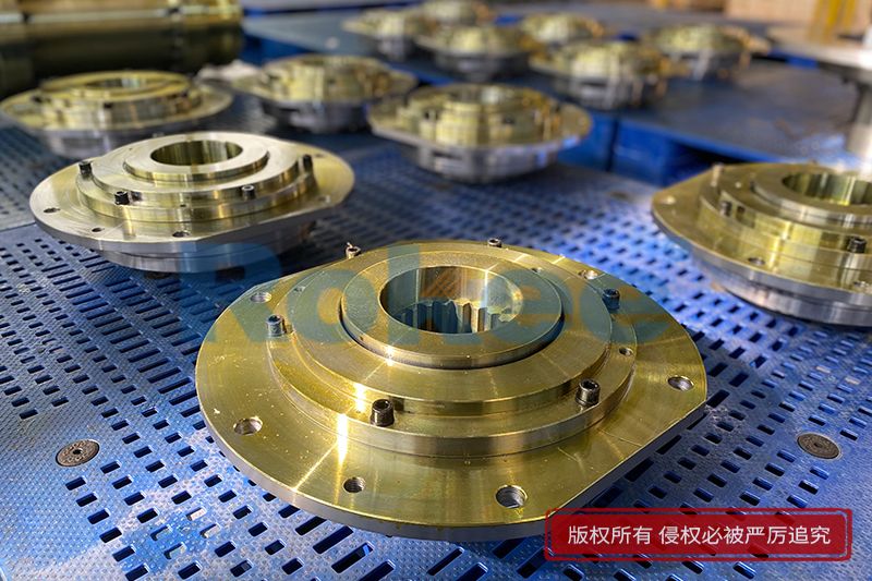
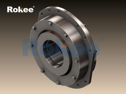
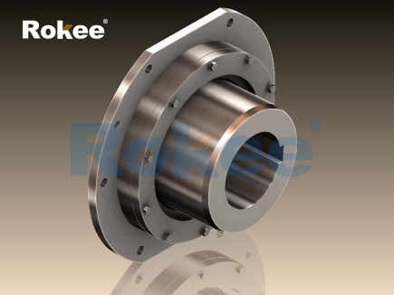
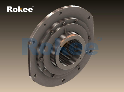
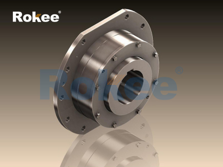
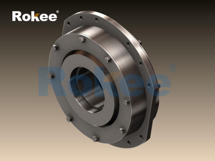
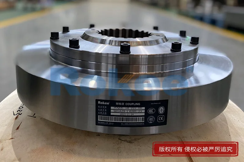
The geometric design of the barrel coupling is another critical aspect of the calculation process. Barrel couplings typically consist of a hub, a barrel (or sleeve), rollers, and sealing components. The hub is connected to the driving and driven shafts, while the barrel houses the rollers that transmit torque between the hubs. The geometry of these components, including the diameter of the hub, the length of the barrel, the size and number of rollers, and the profile of the teeth (if applicable), directly affects the coupling’s torque transmission capacity, misalignment compensation ability, and stress distribution. The calculation of the geometric parameters involves ensuring that the components can accommodate the required misalignments while maintaining uniform stress distribution and avoiding localized stress concentrations, which can lead to premature failure. For example, the length of the barrel must be sufficient to allow for the maximum axial displacement expected in the system, while the diameter of the rollers must be large enough to transmit the design torque without excessive stress.
Stress analysis is a fundamental part of barrel coupling calculation, as it ensures that the components do not exceed their material’s strength limits under the applied loads. The primary stresses acting on barrel coupling components include shear stress, bending stress, and contact stress. Shear stress occurs in the rollers and the hub connections due to the torque transmission, while bending stress is induced by misalignments and radial loads. Contact stress is generated at the interface between the rollers and the barrel, where the load is transmitted through a small contact area. The calculation of these stresses involves using mechanical engineering principles, including shear stress formulas, bending stress equations, and Hertzian contact stress theory for the roller-barrel interface.
Shear stress calculation for the rollers is particularly important, as the rollers are the primary torque-transmitting components. The shear stress in a roller can be calculated using the formula τ = (16T) / (πd³), where τ is the shear stress, T is the design torque, and d is the diameter of the roller. This formula assumes that the torque is uniformly distributed across the rollers, which is a reasonable approximation for well-designed barrel couplings with an adequate number of rollers. However, it is important to ensure that the number of rollers is sufficient to distribute the load evenly, reducing the shear stress in each individual roller. The number of rollers is typically determined based on the design torque, the roller diameter, and the material’s shear strength, with more rollers being used for higher torque applications.
Bending stress in the barrel and hubs is caused by the radial loads and misalignments between the shafts. Radial loads can arise from the weight of the shafts, the components attached to the shafts (such as pulleys or gears), or the operational forces in the system. Angular misalignment between the driving and driven shafts creates a bending moment in the barrel, which induces bending stress. The bending stress can be calculated using the formula σ_b = (M × c) / I, where σ_b is the bending stress, M is the bending moment, c is the distance from the neutral axis to the outer surface of the component, and I is the moment of inertia of the component’s cross-section. For the barrel, the moment of inertia is calculated based on its outer and inner diameters, while for the hubs, it is based on the shaft diameter and the hub’s outer diameter. It is essential to ensure that the bending stress does not exceed the material’s yield strength, as this can lead to permanent deformation or fatigue failure over time.
Contact stress between the rollers and the barrel is another critical factor in barrel coupling calculation. The contact between the roller and the barrel is a point or line contact, depending on the roller’s shape, and the stress at this contact point can be very high. Hertzian contact stress theory is used to calculate this stress, which is given by the formula σ_H = √[(F × E) / (π × b × r)], where σ_H is the Hertzian contact stress, F is the contact force per roller, E is the modulus of elasticity of the material, b is the length of the contact line, and r is the radius of curvature of the roller and the barrel. The contact force per roller is determined by dividing the total radial load and the torque-induced load by the number of rollers. High contact stress can lead to surface fatigue, such as pitting or wear, which can reduce the coupling’s service life. Therefore, the contact stress must be kept below the material’s contact fatigue limit, which is typically a fraction of the material’s tensile strength.
In addition to stress analysis, the calculation of barrel couplings must also consider misalignment compensation. Barrel couplings are designed to accommodate three types of misalignment: angular misalignment (where the shafts are not colinear), parallel misalignment (where the shafts are offset but parallel), and axial misalignment (where the shafts move along their axial direction). The maximum allowable misalignment is a key design parameter that is determined based on the application’s requirements and the coupling’s geometry. Angular misalignment is typically measured in degrees, while parallel misalignment is measured in millimeters (or inches), and axial misalignment is also measured in millimeters (or inches). The calculation of the maximum allowable misalignment involves ensuring that the coupling components do not experience excessive stress or wear when the shafts are misaligned. For example, the length of the barrel and the size of the rollers must be sufficient to allow for the maximum angular misalignment without causing the rollers to bind or the barrel to deform.
Another important aspect of barrel coupling calculation is the consideration of thermal expansion. In many industrial applications, the machinery operates at high temperatures, which causes the shafts and the coupling components to expand thermally. This thermal expansion can lead to axial displacement of the shafts, which must be accommodated by the coupling. The calculation of the thermal expansion involves determining the coefficient of thermal expansion of the material, the operating temperature range, and the length of the shafts. The axial displacement due to thermal expansion is given by ΔL = α × L × ΔT, where ΔL is the axial displacement, α is the coefficient of thermal expansion, L is the length of the shaft, and ΔT is the temperature difference between the operating temperature and the ambient temperature. The barrel coupling must be designed to accommodate this axial displacement without generating additional stresses or reducing the torque transmission capacity.
Fatigue life calculation is also a critical part of barrel coupling design, as couplings are subjected to repeated cycles of stress during their service life. Fatigue failure occurs when the component fails after a certain number of stress cycles, even if the stress is below the material’s yield strength. The fatigue life of a barrel coupling is determined by the fatigue strength of the material, the magnitude of the alternating stress, and the mean stress. The alternating stress is the stress that varies between a maximum and minimum value during each cycle, while the mean stress is the average of these two values. The S-N curve (stress-life curve) of the material is used to determine the number of cycles that the component can withstand before fatigue failure. The S-N curve plots the alternating stress against the number of cycles to failure, and it is used to calculate the fatigue life based on the applied stress levels. To ensure a sufficient fatigue life, the alternating stress must be kept below the material’s fatigue limit, which is the stress level below which the component can withstand an infinite number of cycles without failure.
The calculation process also involves verifying the coupling’s performance under various operating conditions, including extreme loads, temperature variations, and misalignments. This verification can be done using analytical methods, such as finite element analysis (FEA), which provides a detailed analysis of the stress distribution, deformation, and fatigue life of the coupling components. FEA is particularly useful for complex coupling designs or applications with high loads, as it allows for a more accurate representation of the true structure and the applied loads. By modeling the coupling in a CAD software and analyzing it using FEA tools, engineers can identify potential stress concentrations, optimize the geometric design, and ensure that the coupling meets the required performance standards. This iterative process of design and analysis helps to minimize the risk of failure and optimize the coupling’s performance.
In practical applications, the calculation of barrel couplings must also take into account the installation and maintenance requirements. The coupling must be easy to install and align, and it must be accessible for maintenance, such as lubrication or component replacement. The design of the coupling should allow for easy disassembly and reassembly, which reduces downtime and maintenance costs. Additionally, the coupling should be designed to prevent the ingress of dust, dirt, or other contaminants, which can cause wear and corrosion. Sealing components, such as gaskets or O-rings, are often included in the design to protect the internal components from contamination and to retain lubrication, which is essential for reducing friction and wear between the moving parts.
It is also important to consider the compatibility of the barrel coupling with the other components in the transmission system. The coupling must be compatible with the shaft diameters, the keyway dimensions, and the mounting flanges (if applicable). The hub of the coupling must be designed to fit securely on the shafts, with a tight interference fit or a keyed connection to ensure that torque is transmitted efficiently without slippage. The keyway dimensions must be compatible with the keys used to connect the hub to the shaft, and the mounting flanges must be designed to match the flanges of the other components, such as the motor or the gearbox.
The calculation of barrel couplings is a complex process that requires a thorough understanding of mechanical engineering principles, material science, and the specific requirements of the application. It involves multiple steps, including torque calculation, material selection, geometric design, stress analysis, misalignment compensation, thermal expansion consideration, fatigue life calculation, and performance verification. Each of these steps is interdependent, and a mistake in any one step can lead to a coupling that is underdesigned (leading to premature failure) or overdesigned (increasing cost and weight unnecessarily). Therefore, it is essential to approach the calculation process systematically, using accurate data and reliable engineering methods.
In conclusion, barrel coupling calculation is a critical aspect of mechanical design that ensures the reliable and efficient transmission of torque between rotating shafts. By carefully evaluating the torque requirements, material properties, geometric parameters, and operating conditions, engineers can design a barrel coupling that meets the specific needs of the application. The calculation process must account for dynamic loads, misalignments, thermal expansion, and fatigue life to ensure that the coupling operates safely and reliably throughout its service life. With the use of advanced analytical tools, such as finite element analysis, engineers can optimize the design of barrel couplings, reduce the risk of failure, and improve the overall performance of the transmission system. Whether used in cranes, hoists, conveyors, or other industrial machinery, a well-calculated barrel coupling is essential for the smooth and efficient operation of the equipment.
- Tags:
- Barrel Couplings ,
- sandwich panel line ,
- sandwich panel machine
- pu sandwich panel machine
« Barrel Coupling Calculation » Latest Update Date: May 9, 2026
https://www.rokeecoupling.net/blog/barrel-coupling-calculation.html