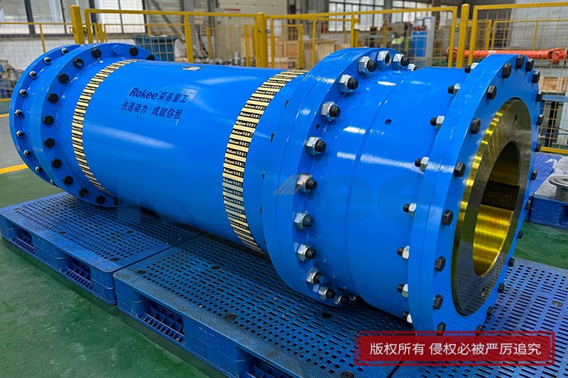
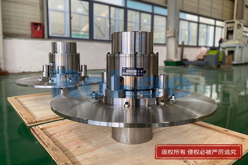
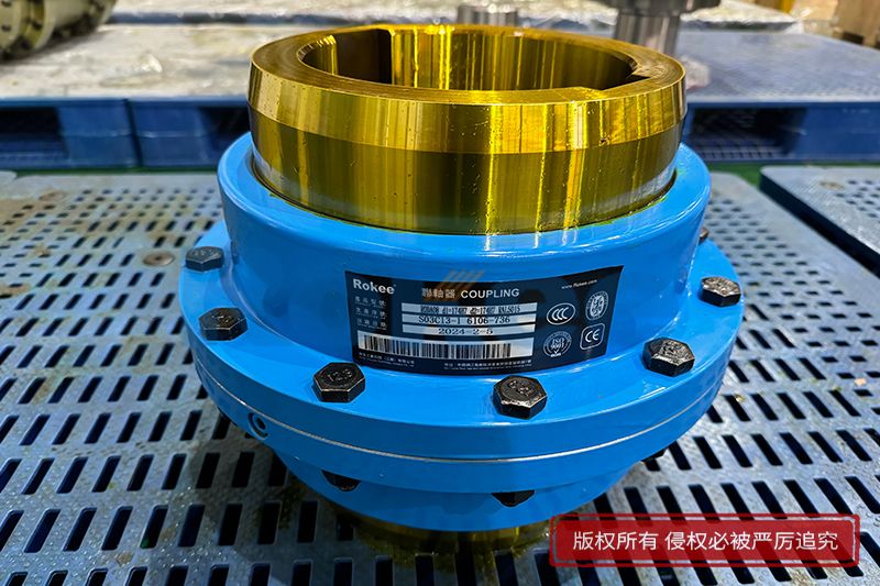
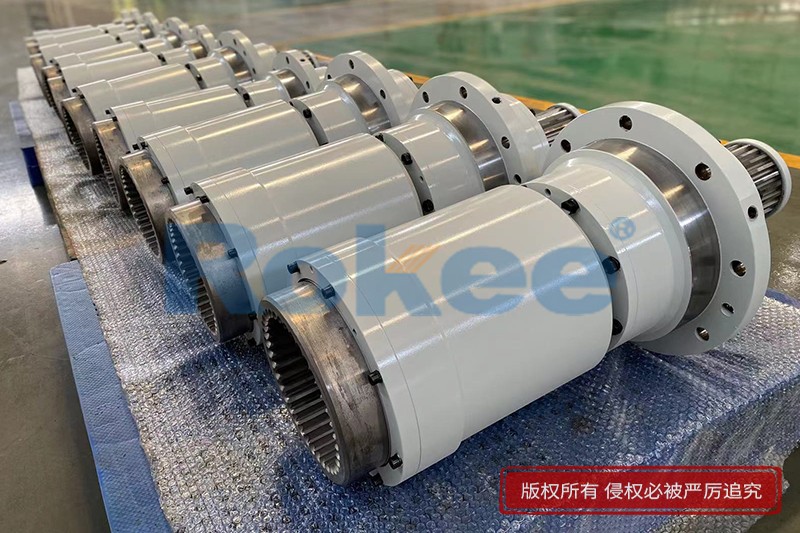
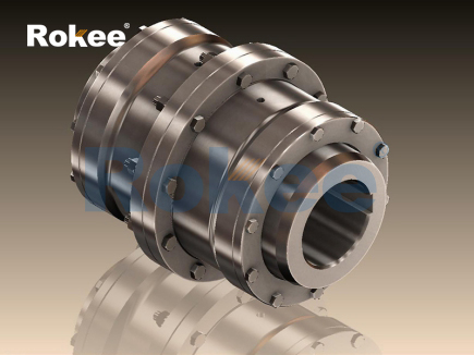
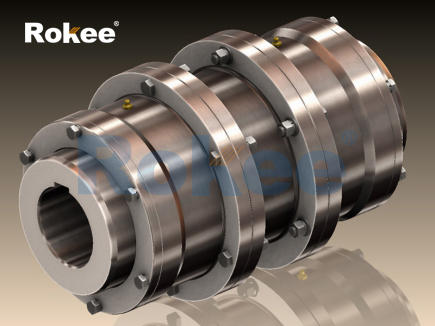
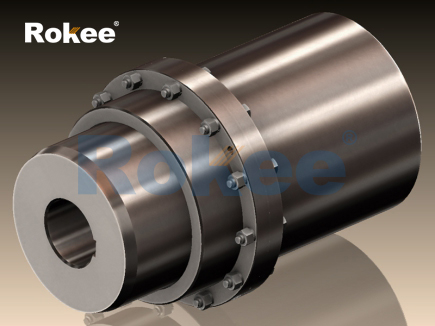
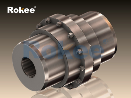
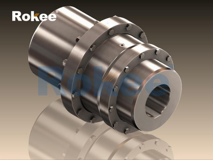
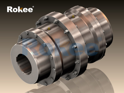
The stable operation of mechanical transmission systems relies heavily on the precise coordination of core components, among which crown gear couplings serve as indispensable connecting parts for torque transmission and shaft connection in various industrial mechanical equipment. As a flexible gear coupling structure with strong load-bearing capacity and certain displacement compensation performance, crown gear couplings can adapt to slight axial, radial and angular deviations in the operation process of mechanical shafts, but this adaptive tolerance is limited. Accurate alignment is the fundamental prerequisite to give full play to the structural advantages of crown gear couplings, avoid abnormal mechanical loss, and ensure the long-term stable and efficient operation of the entire transmission system. Improper alignment is one of the most common causes of premature failure of crown gear couplings and even supporting mechanical equipment, which will trigger a series of adverse chain reactions such as increased equipment vibration, intensified component friction, and reduced transmission efficiency in actual industrial operation.
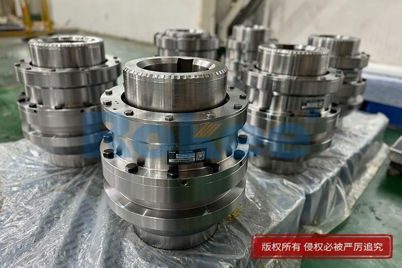
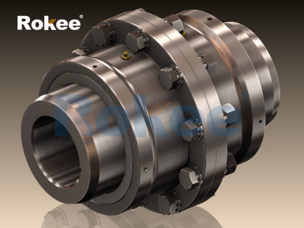
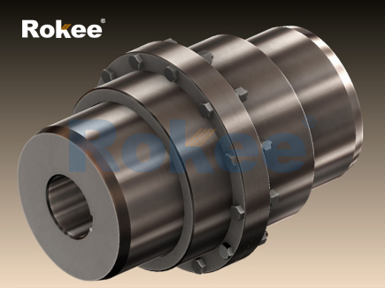
To fully understand the importance of crown gear coupling alignment, it is necessary to clarify the structural operation characteristics of this type of coupling. Different from ordinary rigid couplings, the crown gear coupling adopts the meshing structure of internal gear sleeve and external gear hub, and the crown-shaped tooth profile design enables the gear teeth to have better contact uniformity and deformation buffering performance when bearing torque. This unique structure allows the coupling to bear large rotational torque and impact loads during high-speed operation, but the meshing accuracy of gear teeth is extremely sensitive to the alignment state of the two connected shafts. When the shaft alignment deviates from the standard state, the meshing gap of the gear teeth will be uneven, the local contact pressure of the tooth surface will increase sharply, and the original uniform stress distribution will be completely broken. Long-term operation under such abnormal conditions will lead to gradual wear, pitting and even tooth surface cracking of the gear teeth, which will not only shorten the service life of the coupling itself but also cause additional fatigue load on the connected motor, reducer and other equipment components, accelerating the aging and damage of the entire mechanical system.
In practical industrial application scenarios, the misalignment of crown gear couplings is mainly divided into three basic types, and most equipment failures are caused by the superposition of multiple misalignment states. The first type is radial misalignment, also known as parallel offset misalignment, which refers to the parallel deviation between the central lines of the two connected shafts, that is, the two shaft centers do not coincide and maintain a parallel spacing error. This kind of deviation will cause periodic radial runout during the rotation of the coupling, resulting in continuous alternating shear stress on the gear teeth and shaft body, and produce regular mechanical vibration in the radial direction of the equipment. The second type is angular misalignment, which means that the central lines of the two connected shafts intersect at a certain angle instead of being parallel. Angular deviation will cause uneven axial force on the gear teeth during meshing, resulting in inconsistent contact degree of the tooth surface in different rotation directions, and local excessive friction and extrusion will occur in the rotation cycle. The third type is axial misalignment, which is the excessive or insufficient gap between the two coupling hubs along the shaft axis direction. Unreasonable axial clearance will affect the floating compensation performance of the crown gear coupling, limit its ability to adapt to thermal expansion and contraction of the shaft body during equipment operation, and easily cause axial collision and friction between components. In most on-site working conditions, these three misalignment states often exist simultaneously, forming composite misalignment errors, which bring more complex damage risks to the transmission system.
Complete and standardized pre-alignment preparation is the basis for improving the alignment accuracy of crown gear couplings and ensuring smooth construction. Before carrying out formal alignment measurement and adjustment, it is essential to complete the cleaning and inspection of all coupling components and equipment installation bases. All dust, iron filings, oil stains and rust on the gear tooth surface, hub outer circle, flange end face and shaft surface must be thoroughly removed, because tiny impurities will affect the accuracy of measuring instrument reading and the tightness of component fitting, leading to alignment deviation. At the same time, it is necessary to inspect each component of the coupling to eliminate hidden dangers such as gear tooth damage, surface deformation and thread wear. For the connected mechanical equipment, the stability of the fixed base must be checked first to ensure that the equipment foundation has no loose bolts, uneven settlement or deformation, and the support feet of the equipment are in full contact with the base without virtual cushion state. In addition, the preliminary assembly of the coupling should be completed before alignment. The external gear hubs are stably installed on the two shaft bodies respectively to ensure that the matching degree of the shaft hole and the shaft body meets the operation requirements, the key connection is firm without shaking, and the internal gear sleeve is preliminarily sleeved on the outside of the external gear teeth to complete the preliminary docking of the coupling structure.
At present, the mainstream high-precision alignment methods for crown gear couplings in industrial fields mainly include dial indicator alignment method and laser alignment method, each with applicable working conditions and technical characteristics. The dial indicator alignment method is a traditional and highly reliable measurement mode, which is widely used in conventional equipment debugging and medium and low-speed mechanical transmission scenarios. The core operation principle of this method is to fix the dial indicator support on a stable reference shaft, install two dial indicators respectively corresponding to the radial outer circle and axial end face of the other coupling hub, and realize 360-degree synchronous rotation of the two shafts. In the rotation process, the radial dial indicator can capture the radial runout deviation of the hub, so as to calculate the parallel offset error of the two shafts, while the axial dial indicator measures the end face runout value to judge the angular deviation of the shaft centerline. In the actual measurement process, it is necessary to ensure that the dial indicator probe is in vertical and close contact with the measured surface, the support frame is firmly fixed without shaking and deformation, and the reading is recorded once every quarter rotation to ensure the comprehensiveness and accuracy of the data. It is worth noting that the self-weight deflection of the dial indicator support will cause systematic measurement errors, so it is necessary to correct the support sag error in advance according to the on-site measurement environment to optimize the alignment accuracy.
The laser alignment method is a modern high-precision alignment technology suitable for high-speed, heavy-load and high-precision requirement equipment working conditions. This method uses the laser emitter and receiver installed on the two coupling shafts to form a stable laser reference axis. During the shaft rotation, the instrument automatically collects the offset and angle deviation data of the two shafts, and intuitively displays the misalignment type and deviation value through the data system. Compared with the dial indicator measurement method, laser alignment avoids manual reading errors and support deflection interference, has higher measurement accuracy and faster detection speed, and can accurately identify tiny composite misalignment errors that are difficult to capture by traditional methods. In addition, the laser alignment system can automatically calculate the adjustment amount of the equipment support feet, including the vertical shim thickness and horizontal displacement distance, which greatly improves the efficiency and accuracy of alignment adjustment. Whether adopting dial indicator alignment or laser alignment, the core measurement logic is to quantify radial offset and angular deviation, and take the allowable tolerance range of crown gear coupling operation as the standard to judge whether the alignment state is qualified.
After completing the data measurement and obtaining the specific misalignment deviation value, targeted correction and adjustment operations need to be carried out in strict accordance with the error data. In general mechanical transmission systems, one end of the equipment is fixed as the reference end, and the other end is set as the movable adjustment end to avoid repeated errors caused by simultaneous adjustment of both ends. For radial parallel offset deviation, vertical adjustment is mainly realized by increasing or decreasing gaskets at the support feet of the movable equipment, and horizontal offset is corrected by fine-tuning the horizontal position of the equipment. For angular deviation, it is necessary to adjust the gasket thickness of the front and rear support feet of the movable equipment respectively according to the end face runout data, so that the shaft centerlines of the two equipment can return to the parallel state. For axial misalignment, the relative position of the coupling hub on the shaft body is adjusted to ensure that the axial gap between the two hubs is within the reasonable adaptation range of the crown gear coupling, so as to reserve sufficient floating space for the thermal expansion and contraction of the shaft body during equipment operation.
In the adjustment process, it is necessary to follow the principle of multiple fine adjustments instead of one-time large adjustment. Excessive single adjustment will easily cause new deviation of the reference shaft and damage the original assembly accuracy of the equipment. After each adjustment, re-measurement and data verification must be carried out until all radial, angular and axial deviations are controlled within the standard tolerance range. After the alignment parameters are qualified, the fastening operation of equipment anchor bolts and coupling connecting bolts should be carried out step by step. The bolts need to be tightened symmetrically and gradually to avoid local stress concentration and secondary shaft deviation caused by one-sided excessive fastening. After all bolts are fully tightened, a final comprehensive alignment inspection must be performed again, because the bolt fastening process may cause tiny displacement of the equipment base and shaft body, leading to slight changes in alignment accuracy.
The final commissioning and daily operation verification are important links to test the alignment effect of crown gear couplings. After the completion of alignment and installation, no-load trial operation shall be carried out first. The equipment shall run continuously for a certain period at low speed, and the operation state of the coupling shall be observed in real time, including whether there is abnormal vibration, periodic noise and local heating phenomenon. If the equipment runs smoothly without abnormal state, step-by-step load test operation can be carried out to simulate the actual industrial working condition load, and monitor the vibration amplitude, temperature change and torque transmission stability of the coupling operation. Qualified alignment will make the crown gear coupling have uniform gear meshing state, stable torque transmission, low operation vibration and no abnormal friction noise. On the contrary, if there is continuous high-frequency vibration, local overheating or irregular noise during operation, it indicates that there is residual misalignment error, and secondary fine adjustment and correction are required.
It is important to recognize that the alignment of crown gear couplings is not a one-time construction work, but a dynamic maintenance project that runs through the whole service cycle of the equipment. During the long-term operation of industrial equipment, the vibration of mechanical operation, thermal expansion and contraction of components, aging of equipment foundation and relaxation of fastening bolts will all cause gradual changes in shaft alignment accuracy, leading to secondary misalignment of the coupling. Therefore, regular alignment inspection and calibration must be included in the daily equipment maintenance system. For high-speed and heavy-load equipment with frequent start-stop operation, the alignment state should be checked regularly with a short cycle, and potential tiny deviations should be corrected in time to avoid the accumulation of errors into large-scale misalignment faults. For conventional low-load and stable operation equipment, regular seasonal alignment calibration can effectively maintain the long-term operation accuracy of the coupling.
Reasonable alignment maintenance can not only ensure the efficient transmission performance of crown gear couplings, but also effectively reduce the operation and maintenance cost of mechanical equipment. Accurate shaft alignment minimizes the friction and wear of coupling gear teeth, reduces the generation of fatigue cracks and surface damage, and greatly prolongs the service life of the coupling. At the same time, stable alignment state reduces the additional load and vibration impact on the driving and driven equipment, avoids abnormal loss of bearings, bearings and other supporting components, and reduces the frequency of equipment failure and shutdown maintenance. In addition, good alignment accuracy ensures the optimal meshing state of the crown gear teeth, improves the torque transmission efficiency of the system, reduces the power loss caused by friction and vibration, and realizes energy-saving and efficient operation of mechanical transmission equipment.
In conclusion, the alignment technology of crown gear couplings is a systematic engineering work integrating pre-preparation, precision measurement, scientific adjustment and long-term maintenance. It covers the judgment of misalignment types, the selection of measurement methods, the precise implementation of adjustment operations and the standardized management of daily maintenance. In complex industrial production scenarios, any tiny alignment deviation may be amplified into equipment failure risks in long-term high-load operation. Only by adhering to standardized alignment operation procedures, selecting appropriate precision measurement methods according to actual working conditions, strictly controlling all deviation indicators within the allowable range, and establishing a perfect regular maintenance and calibration mechanism, can the structural performance advantages of crown gear couplings be fully exerted, the stable, efficient and safe operation of the mechanical transmission system be guaranteed, and the long-term reliable operation of industrial production equipment be supported.
- Tags:
- Crown Gear Couplings ,
- sandwich panel line ,
- sandwich panel machine
- pu sandwich panel machine
« Alignment of Crown Gear Coupling » Latest Update Date: Jul 10, 2026
https://www.rokeecoupling.net/blog/alignment-of-crown-gear-coupling.html