Teeth couplings stand as one of the most indispensable rigid movable transmission components in modern mechanical transmission systems, and their structural diagrams intuitively present the exquisite mechanical layout and collaborative assembly relationship of internal components. The structural composition displayed in the diagram is carefully optimized to adapt to complex industrial operating conditions, realizing stable torque transmission, reasonable axis deviation compensation and durable mechanical operation. Observing the complete structural diagram of teeth couplings, people can clearly distinguish multiple core components and auxiliary structures, each of which has a unique mechanical function and interacts with each other to form a complete power transmission unit. Different from other common coupling types, the structural design of teeth couplings focuses on meshing transmission between gear structures, and the dimensional matching and assembly tolerance of each part in the diagram are strictly controlled to ensure high-efficiency and low-loss power transmission in mechanical operation.
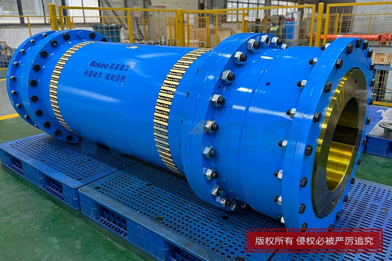
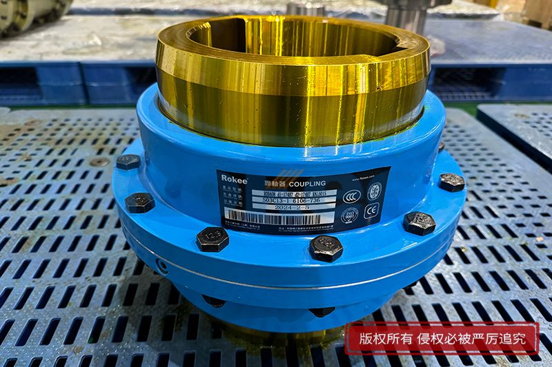
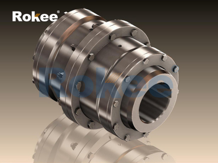
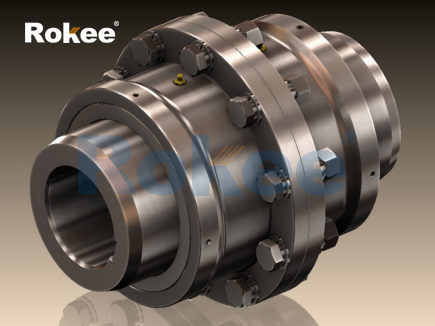
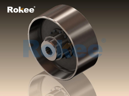
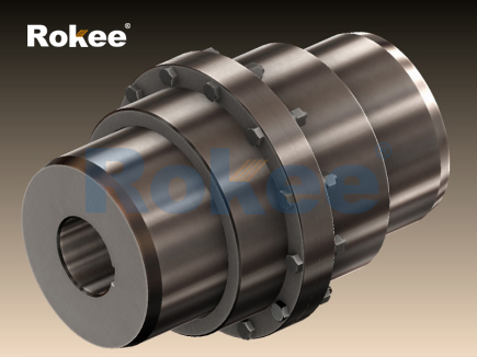
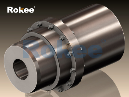
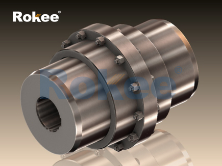
The main components presented in the structural diagram of teeth couplings include outer tooth shaft sleeves, inner gear rings, end covers, sealing components and fastening connecting parts, and the spatial positional relationship of these parts is clearly marked in the diagram to reflect the assembly logic of the coupling. The outer tooth shaft sleeve is the core rotating part connected with the transmission shaft, and its outer edge is processed with uniformly distributed outer teeth, which are the key structures for meshing transmission. In the structural diagram, the outer tooth shaft sleeves are symmetrically distributed on both sides, and the inner wall of the shaft sleeve is designed with smooth shaft holes to facilitate tight nesting with the driving shaft and driven shaft. The tooth shape of outer teeth is divided into straight tooth and crowned tooth, and the structural diagram can visually distinguish the morphological differences between the two tooth types. The crowned tooth has an arc-shaped curved structure on the tooth surface, while the straight tooth maintains a flat and regular tooth profile, and this subtle structural difference brings obvious differences in displacement compensation performance to the coupling.
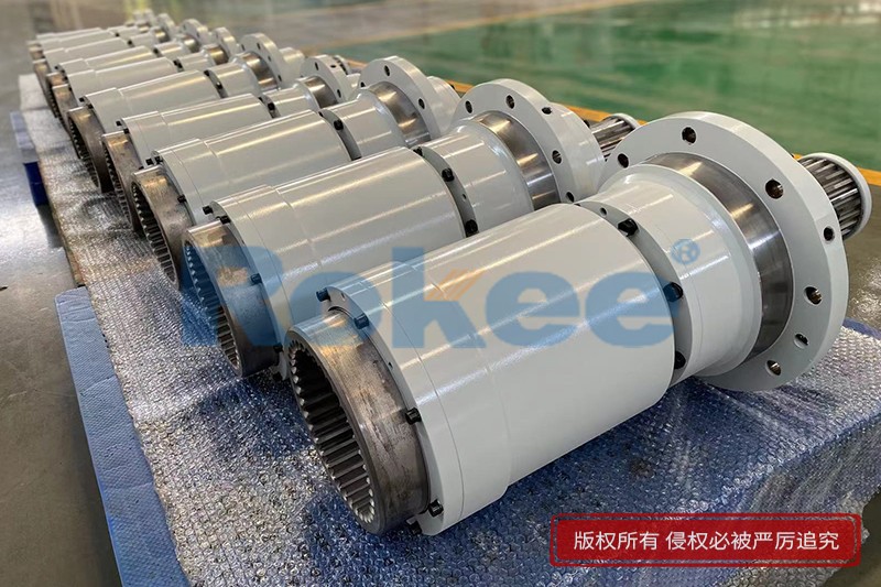
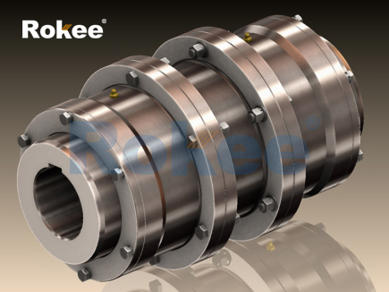
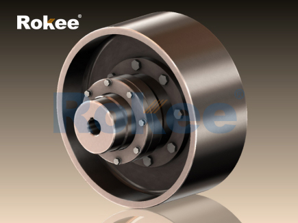
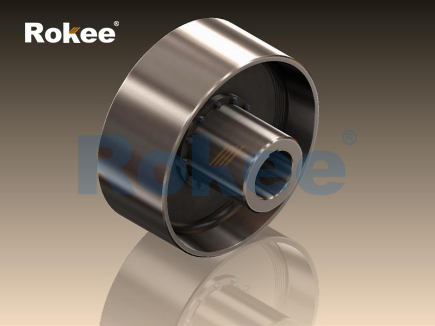
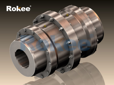
The inner gear ring is matched with the outer tooth shaft sleeve, which is presented as a hollow annular structure in the structural diagram, and the inner wall is distributed with inner teeth that are completely meshed with the outer teeth. The number of inner teeth is consistent with that of outer teeth, ensuring uniform stress on each tooth surface during meshing. From the perspective of structural layout in the diagram, the inner gear ring is sleeved on the outer side of the outer tooth shaft sleeve, wrapping the meshing part of the teeth inside to form a closed transmission space. This wrapping structure not only optimizes the stress distribution of the meshing teeth but also creates a relatively independent space for internal lubrication. The inner gear ring has a thickened wall design in the structural drawing, which enhances the overall structural rigidity and enables it to bear greater instantaneous torque impact during equipment operation. For small-sized teeth couplings, the end cover and the inner gear ring are designed as an integrated structure in the diagram, which simplifies the assembly process and reduces the number of connecting parts, while large-sized couplings adopt a split assembly structure to meet the requirements of heavy-load working conditions.
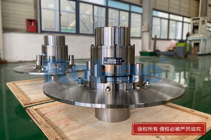
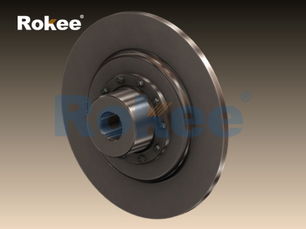
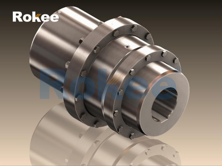
End covers are located at both ends of the inner gear ring in the structural diagram, playing a vital role in limiting the axial position of components and auxiliary sealing. The outline of the end cover is circular, matching the outer diameter of the inner gear ring, and reserved assembly holes are distributed on the edge for penetration and fixing of fastening parts. The inner side of the end cover is closely attached to the end face of the outer tooth shaft sleeve, which can effectively restrict the axial displacement of the shaft sleeve during rotation and avoid component separation caused by axial vibration. The surface of the end cover is smooth and flat, and the structural diagram marks the chamfered structure at the edge to reduce stress concentration during mechanical operation and prevent structural cracking under long-term vibration. In addition, some end covers are designed with reserved lubrication holes in the diagram, which are used for injecting lubricating media into the meshing gap of internal teeth to maintain the lubrication state of the transmission interface.
Sealing components are tiny but essential auxiliary structures in the structural diagram of teeth couplings, which are usually installed at the joint between the end cover and the shaft sleeve as well as the splicing gap of the inner gear ring. These components are presented as thin annular structures in the diagram, made of wear-resistant and oil-resistant elastic materials. The core function of sealing components is to block the leakage of internal lubricants and prevent external dust, metal debris and humid air from invading the meshing area of teeth. In the structural diagram, the installation positions of sealing parts are precisely arranged at the gaps where external impurities are easy to penetrate, forming a multi-layer sealing protection system. Without reasonable sealing structure layout, the lubricating grease inside the coupling will gradually leak, and the dry friction between teeth will accelerate wear, while the intrusion of impurities will cause scratch damage to the tooth surface and reduce the transmission accuracy of the coupling.
Fastening connecting parts include bolts and positioning pins, which are marked as small cylindrical and threaded structures in the structural diagram, evenly arranged along the circumferential direction of the coupling flange. These fastening components connect the end cover, inner gear ring and shaft sleeve into a unified whole, maintaining the stability of the assembly structure during high-speed rotation. The structural diagram reflects the symmetrical distribution characteristics of fastening parts, which can ensure uniform pressure on the connecting surface, avoid local gaps caused by uneven stress, and further strengthen the sealing performance of the coupling. The matching tolerance between fastening parts and assembly holes is extremely strict, and the smooth fit can effectively reduce the vibration amplitude of components during operation and improve the overall operation stability of the coupling.
The tooth profile structure is the most refined part in the structural diagram of teeth couplings, and the tooth spacing, tooth height and tooth thickness of inner and outer teeth are marked with accurate dimensional parameters. The commonly used tooth profile is involute, which has the advantages of smooth meshing process, uniform stress and stable transmission. For crowned teeth couplings, the structural diagram clearly shows the spherical arc shape of the outer tooth surface. This structural improvement enables the teeth to have a larger contact gap during meshing, providing sufficient deformation space for axis deviation. When the connected two shafts have radial displacement, axial displacement or angular deflection, the arc tooth surface can slide appropriately along the contact direction to offset the axis deviation, avoiding rigid stress extrusion between components. In contrast, the straight tooth structure in the diagram has a compact meshing gap, which is suitable for working conditions with high axis alignment accuracy and low deviation amplitude.
By analyzing the assembly combination relationship in the structural diagram, the working transmission principle of teeth couplings can be clearly summarized. In the actual operation process, the driving shaft drives the connected outer tooth shaft sleeve to rotate, and the outer teeth on the shaft sleeve mesh with the inner teeth on the inner gear ring. The friction and extrusion force generated by the meshing tooth surfaces realize the transfer of torque and rotational motion, and then the inner gear ring drives the outer tooth shaft sleeve on the other side to rotate synchronously, finally completing the power transmission between the two shafts. The structural diagram intuitively shows the overlapping meshing state of inner and outer teeth. The large contact area between tooth surfaces enables the coupling to bear high torque load, which is the core reason why teeth couplings are widely used in heavy-duty mechanical equipment. During the transmission process, the tiny gaps reserved in the structural design can store lubricating media, forming a continuous lubricating film on the tooth surface to reduce friction resistance and transmission energy consumption.
The structural characteristics reflected in the diagram endow teeth couplings with unique application advantages compared with other coupling products. First of all, the compact wrapping structure in the diagram makes the coupling occupy a small installation space, and the integrated layout of components is convenient for installation and disassembly in narrow mechanical spaces. Secondly, the optimized tooth profile structure in the diagram gives the coupling excellent axis deviation compensation capability. The crowned tooth structure can adapt to complex deviation conditions, ensuring that the equipment still maintains stable transmission performance when there is installation error or operational vibration deviation. In addition, the thickened tooth body and rigid annular structure in the diagram enhance the structural strength, enabling the coupling to resist instantaneous impact load and avoid tooth breakage or deformation during sudden startup and shutdown of the equipment.
The internal lubrication structure designed in the structural diagram is also an important part to ensure the service life of teeth couplings. The closed cavity formed by the inner gear ring and the end cover is an independent lubrication space, which can store a certain amount of lubricating grease or lubricating oil. The lubrication holes reserved on the end cover facilitate regular oil injection and replacement without disassembling the overall coupling structure. The structural diagram marks the circulation gap of lubricating media between meshing teeth. When the coupling rotates, the flowing lubricant can take away the friction heat generated by the tooth surface, reduce the operating temperature of components, and avoid structural aging and performance degradation caused by high temperature. At the same time, the lubricating medium can form a protective film on the tooth surface to slow down oxidation corrosion and mechanical wear of metal materials.
Different structural forms of teeth couplings have subtle differences in their diagrams to adapt to diverse industrial working conditions. The split teeth coupling is displayed as a bilateral symmetrical split structure in the diagram, which is convenient for separate maintenance and replacement of single-side components and reduces maintenance costs. The integrated teeth coupling simplifies the splicing structure in the diagram, with fewer connecting gaps and higher overall rigidity, suitable for high-speed and stable transmission working conditions. The heavy-duty improved coupling is designed with enlarged tooth thickness and thickened gear ring in the structural diagram, and the number of fastening parts is increased to enhance the bearing capacity, meeting the extreme load transmission requirements of mining, metallurgy and heavy transportation equipment.
In the field of mechanical design and equipment maintenance, the structural diagram of teeth couplings is an important technical reference document. Designers optimize the tooth profile size, component matching gap and overall structural layout according to the transmission load, rotating speed and deviation range of mechanical equipment to customize couplings suitable for specific working conditions. Maintenance personnel judge the wear degree of teeth, aging state of sealing parts and fastening tightness of connecting components based on the structural marking standards in the diagram, formulate reasonable maintenance cycles and replacement plans, and eliminate potential mechanical failures in advance. The standardized structural marking in the diagram also provides a unified reference for batch production and processing of couplings, ensuring the dimensional consistency and assembly interchangeability of finished products.
Although the structural design of teeth couplings is mature and stable, there are still continuous optimization spaces based on the existing structural diagram. In the modern mechanical industry, designers optimize the arc curvature of crowned teeth and the smoothness of tooth surface processing on the basis of the original structural diagram to further reduce meshing friction and vibration noise. Some improved structures add auxiliary diversion grooves inside the inner gear ring in the diagram to accelerate the circulation of lubricating media and improve heat dissipation efficiency. In addition, the structural optimization of sealing components is carried out to enhance the adaptability of couplings to high-temperature, low-temperature and humid corrosive environments, expanding the application scope of teeth couplings in special industrial fields.
In conclusion, the structural diagram of teeth couplings systematically displays the component composition, spatial layout, meshing relationship and structural optimization details of this mechanical transmission part. Each structural unit in the diagram has clear functional positioning, and the cooperative operation of multiple components realizes efficient torque transmission, reliable deviation compensation and durable mechanical operation. With the advantages of compact structure, strong bearing capacity and convenient maintenance, teeth couplings have become an important basic component in industrial transmission systems. In the future, with the continuous progress of mechanical processing technology, the structural design of teeth couplings will be further optimized on the basis of the existing diagram structure to adapt to higher-standard industrial operating conditions, providing more stable and efficient transmission support for the development of modern mechanical engineering.
- Tags:
- Teeth Couplings ,
- sandwich panel line ,
- sandwich panel machine
- pu sandwich panel machine
« Structural Diagram of Teeth Couplings » Latest Update Date: May 14, 2026
https://www.rokeecoupling.net/blog/structural-diagram-of-teeth-couplings.html