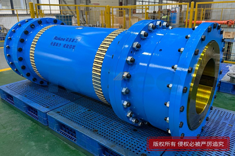
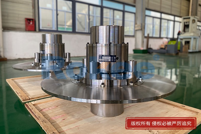
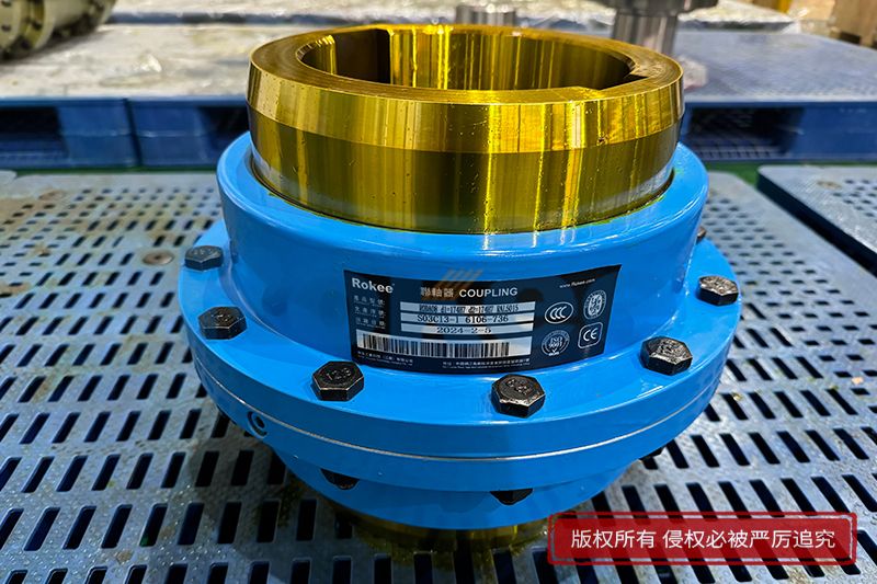
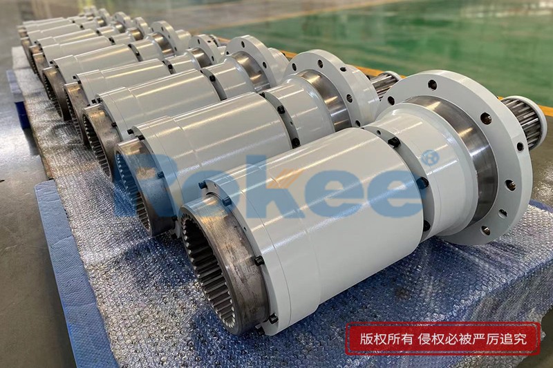
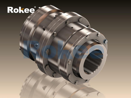
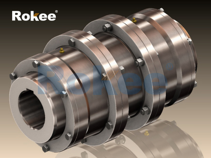
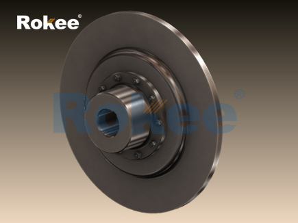
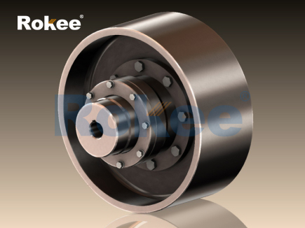
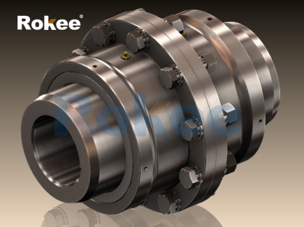
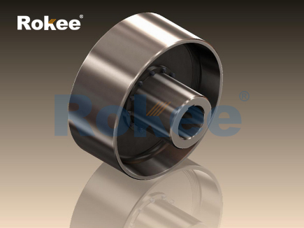
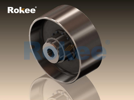
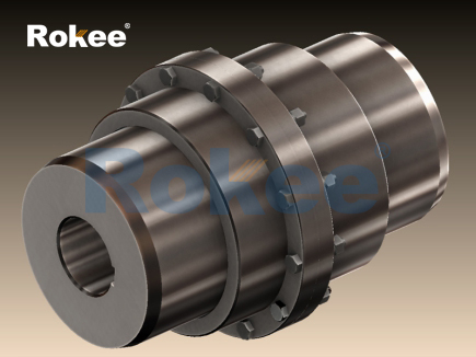
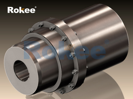
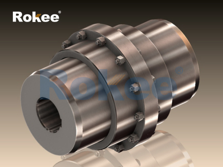
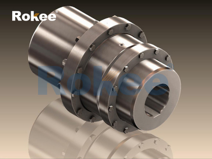
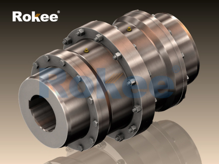
The tooth coupling stands as a flexible mechanical connection device designed to transmit rotational torque between two shafts while accommodating minor misalignments that inevitably arise during equipment operation. At its core, the basic structure consists of two hubs with external gear teeth and a surrounding sleeve fitted with internal gear teeth, where the outer teeth of the hubs mesh with the inner teeth of the sleeve to form a continuous power transmission path. Unlike rigid couplings that require near-perfect shaft alignment, the curved profile of the gear teeth creates a controlled sliding contact surface when the connected shafts deviate from a coaxial line. This special tooth geometry allows limited angular, radial, and axial displacement without imposing excessive stress on the connected machinery. When the driving shaft rotates, torque transfers from the driving hub’s outer teeth to the internal teeth of the sleeve, and then onward to the outer teeth of the driven hub, which in turn spins the driven shaft. Lubrication fills the small gaps between meshing teeth to reduce metal-to-metal friction and wear during repeated engagement. Without this lubricating medium, the sliding motion between tooth surfaces would quickly generate high heat and abrasive damage, shortening the service life of the coupling assembly. Even under steady load conditions, slight vibration from rotating components creates constant micro-movement between tooth contact areas, and the lubricant layer cushions these small impacts to maintain stable power transfer. The design balances rigid torque transmission capability with the flexibility needed to compensate for alignment errors that develop from manufacturing tolerances, thermal expansion, or gradual settling of equipment foundations over time.
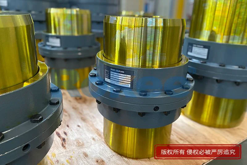
The tooth profile forms the most critical factor that defines the working behavior of a tooth coupling, distinguishing its performance from other gear-based transmission components. Most tooth couplings adopt crowned external teeth, meaning the tooth surface curves along the length of each tooth instead of remaining straight and flat. This crowned shape enables the teeth to pivot gently within the sleeve’s internal teeth when shaft misalignment occurs, rather than concentrating contact pressure on a narrow edge of the tooth. Straight gear teeth would bear heavy edge loads under misalignment, leading to localized pitting, cracking, and premature tooth failure. The curvature distributes contact stress across a wider area of the tooth face, lowering peak pressure and allowing smooth sliding as the coupling flexes. As the shafts rotate out of perfect alignment, each tooth shifts its contact point continuously across the crowned surface during every full rotation. This cyclic contact movement does not interrupt torque delivery, but it introduces a small amount of relative sliding between mating tooth surfaces. The magnitude of sliding increases as misalignment grows, which directly raises frictional heat and wear rates. Engineers must evaluate the expected operating misalignment range to select appropriate tooth curvature, because excessive misalignment will overwhelm the designed flexibility and accelerate component degradation. The tooth depth and number of teeth also influence load distribution; a greater number of teeth spreads total torque across more contact points, though manufacturing precision becomes more demanding to ensure uniform load sharing across all meshing pairs.
Load transfer within a tooth coupling follows a dynamic cyclic pattern that changes with rotation speed and applied torque magnitude. Under low torque conditions, contact may only occur on a subset of the available gear teeth due to tiny manufacturing irregularities between individual tooth profiles. As transmitted torque rises, tooth deflection increases, bringing additional teeth into contact and distributing the load across more meshing surfaces. This progressive load sharing prevents a small number of teeth from carrying the full operational load at all times. When torque fluctuates, such as during startup, sudden load spikes, or cyclic operating conditions, the tooth contact zones shift rapidly. The elastic deformation of gear teeth absorbs transient shock loads before these forces transfer fully to the connected shafts and bearings. This shock damping capability makes tooth couplings suitable for equipment that experiences intermittent loading, though their ability to absorb shock remains limited compared to elastomeric flexible couplings. During continuous rotation, each tooth pair engages and disengages cyclically, creating repeated compressive stress on the contact surfaces. Surface fatigue becomes a primary failure mode under long-term cyclic loading, as repeated compression gradually creates microcracks on the tooth contact layer. These microcracks can expand and form surface pits if lubrication deteriorates or load levels consistently exceed the design range. Proper matching of coupling size to peak and continuous operating torque is essential to avoid permanent plastic deformation of the gear teeth, which would destroy the precision meshing geometry and eliminate the coupling’s ability to accommodate misalignment.
Misalignment accommodation represents the primary functional advantage of tooth couplings, and understanding how each type of misalignment interacts with meshing teeth reveals the boundaries of their operating capability. Angular misalignment occurs when the centerlines of the two connected shafts intersect at a small angle rather than running parallel. The crowned tooth geometry permits the hub teeth to tilt within the sleeve, maintaining partial contact without binding. Radial misalignment takes place when shaft centerlines remain parallel but are offset sideways. In this case, the meshing teeth slide radially inside the sleeve during rotation, and the sliding distance depends directly on the offset amount. Axial misalignment arises from thermal expansion of shafts or minor movement of equipment casings, and the tooth coupling allows limited axial movement as the hub teeth slide deeper or shallower into the sleeve’s internal gear. All three forms of misalignment usually appear simultaneously in real installations, and their combined effect increases cumulative sliding between mating teeth. Every instance of relative sliding consumes power through friction and generates heat, which accumulates inside the coupling enclosure. If total misalignment exceeds the designed allowable value, tooth contact becomes concentrated on sharp edges, friction rises sharply, and heat buildup can break down lubricant rapidly. Even within the rated misalignment range, higher operating speeds amplify the consequences of sliding friction, raising operating temperature and wear rates. Operators should aim to minimize installation misalignment as much as practical, using the coupling’s flexibility only to compensate for unavoidable residual displacement instead of treating it as a tolerance for careless alignment work.
Lubrication is inseparable from the working principle of tooth couplings, as the lubricant performs multiple essential roles beyond simple friction reduction. A continuous oil or grease film separates the metallic surfaces of internal and external teeth during operation, preventing direct metal contact that would cause scuffing and rapid material loss. The lubricant also acts as a heat transfer medium, drawing thermal energy generated by sliding friction away from tooth contact zones and dissipating it through the coupling sleeve to the surrounding atmosphere. Solid particles created by slow wear of tooth surfaces become suspended within the lubricant, preventing abrasive debris from becoming trapped between meshing teeth and scratching the polished contact surfaces. Different lubricant types suit different operating conditions; thicker grease stays in place more easily in stationary or low-speed couplings, while fluid oil circulates better and removes heat more effectively for high-speed continuous operation. Over time, thermal stress and mechanical shearing break down lubricant properties. Oxidation creates sticky residues that coat tooth surfaces and block proper sliding movement, while contamination from water or dust degrades the protective film strength. When lubricant fails, the protective layer disappears, and metal-on-metal contact begins almost immediately. The rate of wear accelerates exponentially, and localized hot spots can even cause tooth softening. Seals fitted at the two ends of the sleeve retain lubricant inside the coupling housing and block external contaminants from entering. Damaged seals allow lubricant leakage and ingress of dirt, which is one of the most common causes of premature tooth coupling failure in field applications.
Dynamic behavior during rotational operation introduces subtle mechanical effects that shape the overall performance of tooth coupling assemblies. At steady rotational speed, the mass of the sleeve and hubs creates centrifugal force that pushes lubricant outward toward the inner wall of the sleeve. This natural distribution helps maintain lubrication coverage on the internal gear teeth, but at extremely high speeds, lubricant may accumulate heavily at the outer diameter and leave insufficient oil at the tooth roots. Rotational vibration interacts with the meshing gear teeth, producing small fluctuations in contact pressure for every rotation. When operating speed approaches certain critical frequencies, resonance can amplify vibration amplitudes, increasing tooth stress and accelerating wear. Unlike elastomeric couplings, tooth couplings have relatively high torsional stiffness, meaning they resist angular twisting under applied torque. This high torsional stiffness keeps shaft rotation synchronized, making tooth couplings ideal for applications requiring precise rotational phase control between driving and driven equipment. However, high torsional stiffness also means the coupling cannot filter out low-frequency torsional vibration as effectively as couplings with rubber or polymer elements. Any torsional oscillation from the prime mover transfers through the coupling with minimal attenuation, which may require additional vibration control measures elsewhere in the drive train. Balancing of the coupling components is important for high-speed use; unbalanced mass creates cyclic radial forces that increase bearing loads and worsen shaft misalignment over extended running periods. Regular monitoring of vibration levels can reveal early signs of tooth wear, lubricant loss, or shifting shaft alignment before catastrophic failure occurs.
Degradation mechanisms define the practical service limits of tooth couplings and illustrate how working conditions gradually erode their ability to transmit torque and accommodate misalignment. Surface pitting starts as microcracks on tooth contact surfaces caused by repeated compressive loading cycles. As cracks expand, small flakes of material separate from the tooth surface, leaving pits that disrupt the smooth contact profile. Once pitting develops, the load distribution across teeth becomes uneven, speeding up further damage. Scuffing occurs when lubricant film fails under high pressure or temperature, welding tiny spots of metal between mating teeth. Subsequent rotation tears these welded points, leaving rough, damaged tooth surfaces. Tooth breakage represents a more severe failure mode, typically caused by overload, severe misalignment, or deep crack propagation from tooth roots. Wear gradually reduces the thickness of gear teeth over time, increasing backlash between mating components. Rising backlash leads to impact loads when torque direction reverses, creating sharp shocks that damage both the coupling and connected bearings. Corrosion can also degrade tooth surfaces if moisture enters the coupling housing through defective seals. Oxidized corrosion products are abrasive and scratch tooth surfaces, further damaging the lubricant film. Many of these damage modes progress slowly at first and remain hidden inside the sleeve, where visual inspection is not possible without disassembly. For this reason, condition monitoring techniques that track temperature, vibration, and lubricant quality are valuable for identifying early degradation trends. Recognizing the early warning signs allows maintenance teams to address root causes such as excessive misalignment or degraded lubricant before irreversible damage to the gear teeth takes place.
Comparative evaluation of tooth couplings against other flexible coupling types helps place their working principle and functional tradeoffs into a broader mechanical context. Elastomeric couplings rely on compression and shear deformation of flexible polymer inserts to absorb misalignment and vibration, but they have lower torque density and narrower temperature limits. In contrast, tooth couplings use metal-on-greased contact surfaces to transmit torque, delivering much higher torque capacity within a compact physical size. This high torque-to-dimension ratio makes them attractive for heavy-duty industrial drives where space is constrained. Diaphragm couplings use thin metallic plates to flex and accommodate misalignment with almost no sliding between contact surfaces, reducing wear and lubrication needs. However, diaphragm couplings are less tolerant of axial displacement and often come with more sensitivity to shock loads. Chain couplings transmit torque through interlocking chain links wrapped around sprocket hubs, offering simplicity but higher noise and vibration during operation. Tooth couplings sit between these alternatives, combining high torque capacity, good misalignment capability, and a dependence on proper lubrication. Their main limitation comes from the inherent sliding motion between gear teeth, which creates wear and heat, requiring planned lubricant maintenance. Applications with frequent torque reversals or extreme shock loads must account for the impact forces acting on meshing teeth. Where low maintenance and zero lubrication are top priorities, other coupling designs may be preferable. In heavy rotating machinery with steady or moderately fluctuating torque, tooth couplings continue to serve reliably when installed correctly, aligned reasonably well, and maintained with regular lubricant replacement and seal inspection, leveraging their fundamental gear meshing principle to maintain dependable power transmission across decades of industrial use.
- Tags:
- Curved Tooth Couplings ,
- Tooth Couplings ,
- sandwich panel line ,
- sandwich panel machine
- pu sandwich panel machine
« Working Principle of Tooth Couplings » Latest Update Date: Oct 20, 2026
https://www.rokeecoupling.net/blog/working-principle-of-tooth-couplings.html