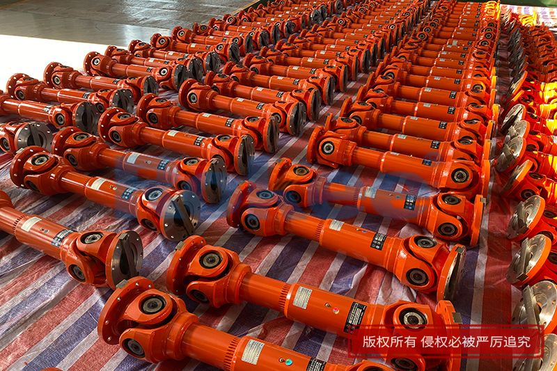
The cardan drive shaft stands as one of the most fundamental and widely applied mechanical transmission components in modern mechanical systems, undertaking the critical task of transmitting rotational power between two shafts with non-coaxial spatial positions. The operating angle of the cardan drive shaft serves as a core parameter that determines its transmission performance, mechanical stability, and service life. This angle refers to the included angle formed between the central axes of the driving shaft and the driven shaft connected by the universal joint, and it inevitably appears during the assembly and operation of mechanical equipment due to structural layout limitations and dynamic displacement changes. Even minor variations in this angular value can trigger noticeable changes in transmission efficiency, vibration amplitude, and stress distribution of the entire transmission system, making an in-depth exploration of the cardan drive shaft angle essential for optimizing mechanical design, improving operating conditions, and reducing component wear. Throughout various mechanical application scenarios, the reasonable control of the shaft angle has become a key technical indicator to ensure the reliable operation of power transmission structures.
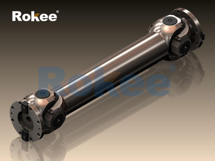
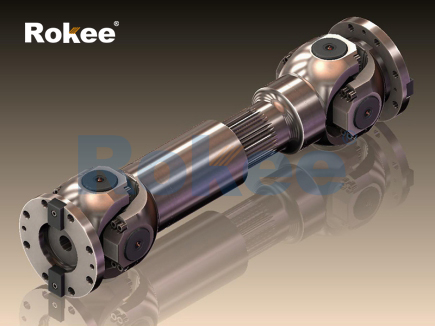
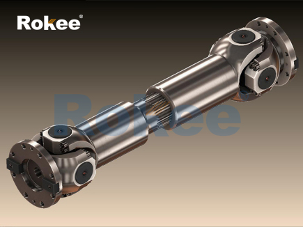
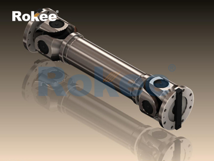
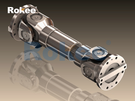
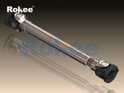
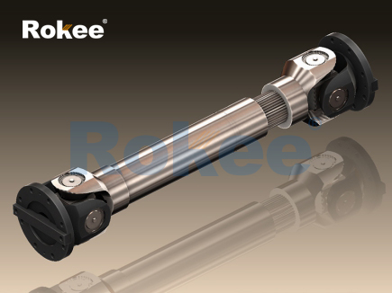
To comprehensively understand the working mechanism of the cardan drive shaft angle, it is necessary to start with the basic structural composition of the cardan transmission mechanism. A typical cardan drive shaft system mainly consists of universal joint yokes, cross shafts, needle bearings, and intermediate transmission shafts. The cross shaft acts as the core connecting component, linking the driving yoke and the driven yoke to realize the flexible transmission of power between spatially staggered shafts. When the mechanical equipment is in operation, the driving shaft drives the cross shaft to rotate through the driving yoke, and the cross shaft further transmits torque to the driven yoke and the driven shaft. The existence of the shaft angle enables the transmission system to adapt to position deviations between adjacent shafts caused by structural installation, mechanical deformation, or external load impacts. In the static assembly state, the fixed installation angle formed by the two shafts is defined as the static installation angle, while the dynamic deflection angle generated during equipment operation due to structural vibration and component displacement is the dynamic working angle. Both types of angles jointly affect the operating state of the cardan drive shaft and cannot be ignored in mechanical analysis.
The most prominent mechanical characteristic brought by the cardan drive shaft angle is the non-uniform speed transmission property of a single rigid universal joint. When there is an included angle between the driving shaft and the driven shaft, even if the driving shaft maintains a constant angular velocity rotation, the instantaneous angular velocity of the driven shaft will fluctuate periodically within one rotation cycle. This phenomenon originates from the spatial motion constraint of the cross shaft structure. During the rotation process, the force-bearing arm of the cross shaft changes continuously with the rotation angle, leading to regular variations in torque transmission efficiency. The fluctuation range of the instantaneous angular velocity is positively correlated with the magnitude of the shaft angle; the larger the included angle between the two shafts, the more intense the angular velocity fluctuation of the driven shaft, and the more obvious the non-uniform transmission effect. Although the average rotational speeds of the driving shaft and the driven shaft remain consistent in a complete rotation cycle, the periodic instantaneous speed difference will induce alternating torsional loads inside the transmission components.
These alternating loads derived from the shaft angle fluctuation will exert multiple adverse effects on the mechanical performance of the transmission system. First of all, periodic torsional vibration will be generated in the driven shaft and its connected mechanical components. The vibration frequency is synchronized with the rotation frequency of the drive shaft, and the vibration amplitude increases with the expansion of the shaft angle. Long-term high-frequency vibration will cause micro-deformation and fatigue damage to metal components, accelerating the wear of needle bearings, cross shafts, and yoke connection parts. Secondly, the angular velocity fluctuation will produce additional mechanical noise during the operation of the equipment. The friction and collision between internal components caused by vibration form continuous operating noise, which not only reduces the mechanical operation comfort but also indicates the energy loss inside the system. Furthermore, excessive shaft angles will significantly reduce the power transmission efficiency of the cardan drive shaft. Part of the mechanical energy is consumed in the form of vibration friction and structural deformation, resulting in insufficient power output of the transmission system and increased energy consumption during equipment operation.
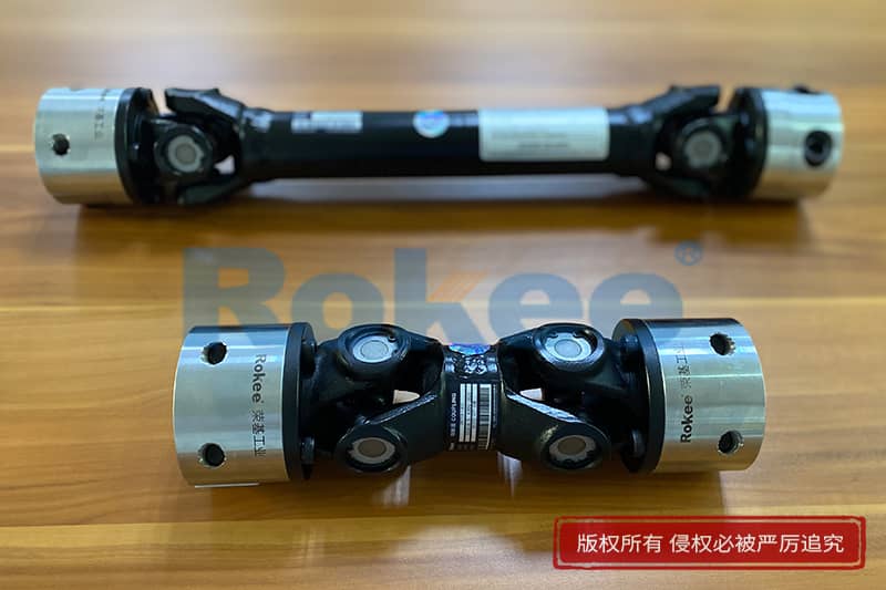
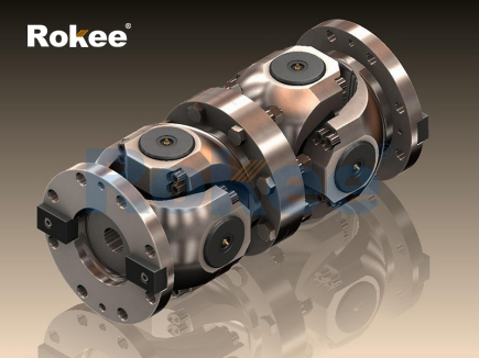
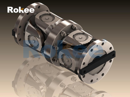
In practical mechanical design, the single universal joint structure is rarely used alone in high-precision and high-load transmission scenarios due to its inherent non-uniform speed defect. The double universal joint transmission configuration has become the mainstream optimization method to eliminate the adverse impact of the shaft angle. This structure arranges two universal joints at both ends of the intermediate transmission shaft, and by reasonably adjusting the installation positions and angles of the two joints, the included angles between the driving shaft and the intermediate shaft as well as between the intermediate shaft and the driven shaft are kept equal. Following the motion compensation principle of the universal joint, the non-uniform speed generated by the first universal joint during rotation can be completely offset by the reverse speed fluctuation of the second universal joint. This structural design effectively realizes the constant-speed transmission of the overall system, fundamentally weakening the torsional vibration and additional load caused by the shaft angle, and greatly improving the transmission stability of the cardan drive shaft. Meanwhile, the intermediate shaft between the two universal joints can appropriately buffer the axial displacement and angular deviation of the system, further enhancing the environmental adaptability of the transmission structure.
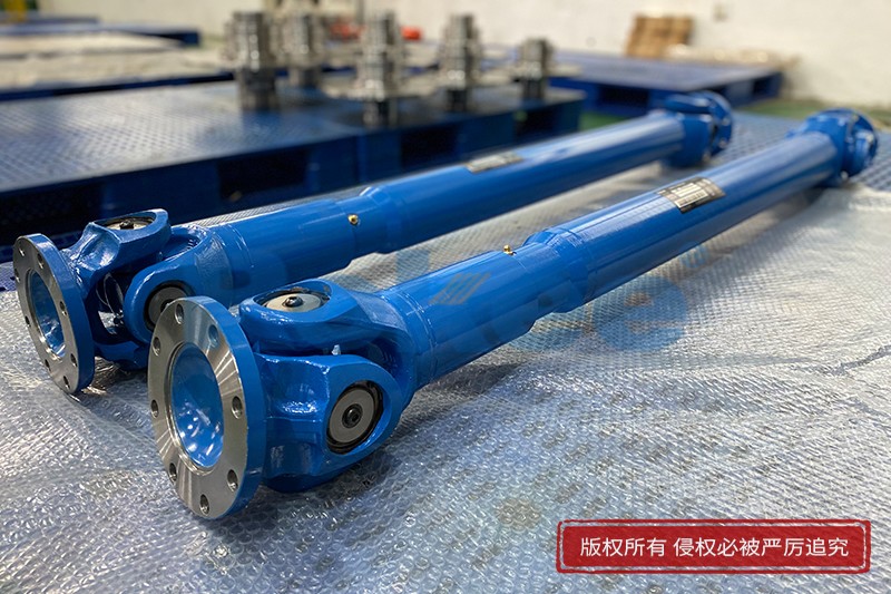
The reasonable range of the cardan drive shaft angle varies according to different structural forms and application working conditions. For the commonly used cross-shaft rigid universal joint, the safe working angle of a single joint is usually limited within a narrow interval. Excessively small angles cannot make full use of the flexible connection advantage of the universal joint, making it difficult to adapt to the minor position deviation of the mechanical structure; excessively large angles will intensify the non-uniform speed effect and bring irreversible fatigue damage to the components. In conventional ground mobile machinery, the static installation angle of the double universal joint transmission system is generally controlled at a low level to ensure smooth power transmission under stable driving conditions. For special operating machinery with complex working conditions such as uneven bearing surfaces and frequent structural jitter, the allowable dynamic working angle can be appropriately increased within the mechanical strength limit to adapt to the drastic spatial position changes between shafts.
Many external and internal factors jointly affect the variation of the cardan drive shaft angle. In terms of installation factors, the assembly accuracy of mechanical frames, the flatness of component mounting surfaces, and the reserved assembly gaps will directly determine the initial static angle of the drive shaft. Low installation precision will lead to excessive initial deflection angles, leaving hidden dangers for subsequent equipment operation. In terms of working conditions, the changes in external loads will cause elastic deformation of mechanical brackets and connecting components, thereby driving the relative displacement of the connected shafts and dynamically increasing the shaft angle. The vibration generated by the mechanical movement on uneven working surfaces will also produce instantaneous angular deflection, resulting in frequent fluctuations of the working angle within a certain range. In addition, the thermal deformation of metal components caused by long-term high-load operation will change the spatial relative position of the shafts, leading to slow drift of the static installation angle and affecting the long-term operating stability of the transmission system.
To mitigate the negative impacts of unreasonable shaft angles, systematic optimization measures need to be implemented from the aspects of structural design, installation process, and daily maintenance. In the structural design stage, designers should accurately calculate the spatial motion trajectory of each component according to the mechanical operation stroke and working environment, pre-set a reasonable initial installation angle, and reserve a safe fluctuation range for dynamic angles. The length of the intermediate drive shaft should be optimized to avoid excessive shaft vibration caused by an overlong shaft body, which indirectly prevents abnormal increases in the deflection angle. For mechanical equipment with large angle variation requirements, high-strength flexible universal joint structures can be selected to improve the deformation resistance and angle adaptation capability of the components. In the equipment installation process, precision measuring tools are used to calibrate the coaxiality and deflection angle of the shafts to eliminate installation errors and ensure that the initial angle is within the optimal design range.
Daily maintenance and detection also play an indispensable role in controlling the cardan drive shaft angle. During the regular maintenance of mechanical equipment, the connection tightness of the universal joint fasteners should be inspected to prevent the displacement of fixed components from causing angle deviation. The wear degree of internal bearings and cross shafts should be checked regularly; severely worn components will increase the structural clearance, leading to unstable shaft angles and aggravated vibration. For mechanical equipment that has been operated for a long time, professional angle calibration is required to correct the static angle drift caused by metal fatigue and thermal deformation. Meanwhile, good lubrication conditions should be maintained inside the universal joint. High-quality lubricants can reduce the friction coefficient between components, weaken the vibration amplitude induced by angular deviation, and delay the fatigue aging speed of metal materials.
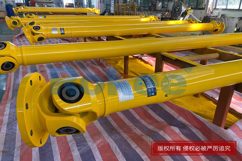
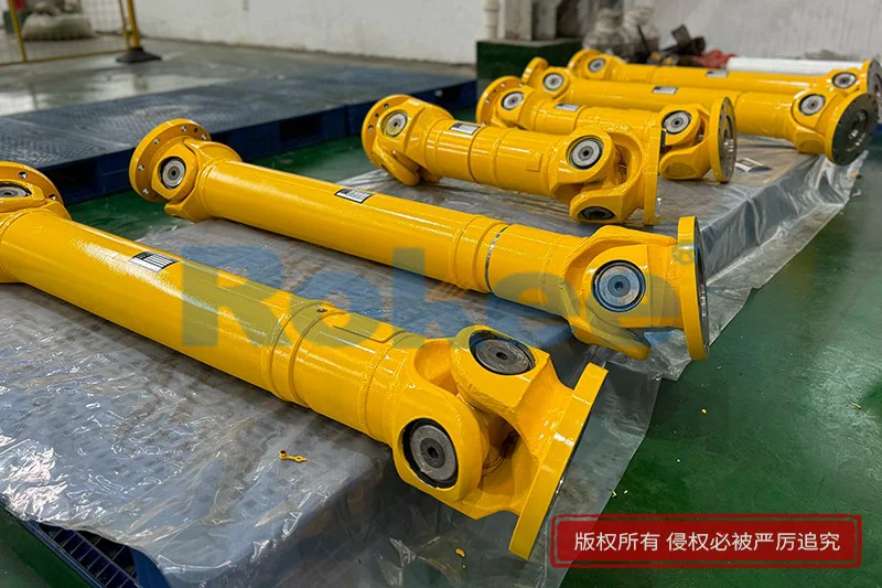
In different industrial application scenarios, the control standards for the cardan drive shaft angle have distinct directional emphases. In transportation machinery represented by traditional rear-drive vehicles, the drive shaft needs to adapt to the vertical jitter of the drive axle caused by uneven road surfaces. Therefore, the dynamic angle design focuses on vibration buffering and smooth power output to ensure driving comfort and power stability. In engineering machinery such as loaders and excavators, the transmission system needs to bear heavy loads and frequent structural position changes, so the shaft angle design prioritizes structural strength and impact resistance, allowing a larger safe deflection angle. In precision industrial transmission equipment, the requirement for transmission stability is extremely high, and the shaft angle needs to be strictly controlled at an ultra-low level to eliminate vibration interference and ensure the accurate transmission of motion parameters.
With the continuous progress of mechanical manufacturing technology, the optimization research on the cardan drive shaft angle is moving towards refined calculation and intelligent regulation. Modern mechanical simulation technology can construct a dynamic model of the drive shaft angle, simulate the angle fluctuation law under complex working conditions, and predict the fatigue life of components under different angular loads. This digital analysis method effectively shortens the product design cycle and improves the rationality of angle parameter setting. At the same time, some novel composite materials and optimized joint structures are gradually applied to the production of cardan drive shafts. These advanced designs can reduce the structural stress sensitivity to angular deviation, improve the tolerance of the transmission system to angle changes, and further expand the application scope of cardan transmission mechanisms.
In conclusion, the operating angle is an indispensable core parameter of the cardan drive shaft system, which profoundly affects the transmission efficiency, mechanical vibration, component wear, and overall stability of the power transmission structure. The non-uniform speed transmission characteristic caused by the shaft angle is the essential mechanical attribute that needs to be focused on in design and application. Through the reasonable application of double universal joint structures, precise installation calibration, scientific daily maintenance, and targeted optimization according to application scenarios, the adverse effects of angular deviation can be effectively suppressed, and the efficient and reliable operation of the cardan drive shaft can be guaranteed. In the future development of mechanical engineering, with the continuous innovation of simulation analysis technology and manufacturing processes, the angle control accuracy of cardan drive shafts will be further improved, providing more stable and durable power transmission solutions for various mechanical equipment. In all mechanical scenarios involving flexible shaft connection, the in-depth study and precise control of the cardan drive shaft angle will always be an important technical guarantee to promote the stable operation and performance upgrading of mechanical systems.
- Tags:
- Cardan Drive Shafts ,
- sandwich panel line ,
- sandwich panel machine
- pu sandwich panel machine
« Angle of Cardan Drive Shaft » Latest Update Date: May 21, 2026
https://www.rokeecoupling.net/blog/angle-of-cardan-drive-shaft.html