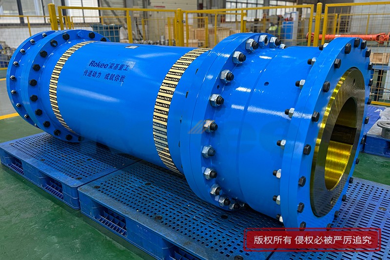
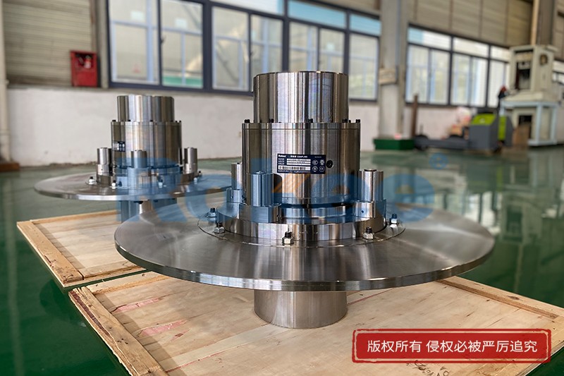
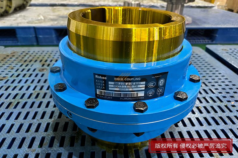
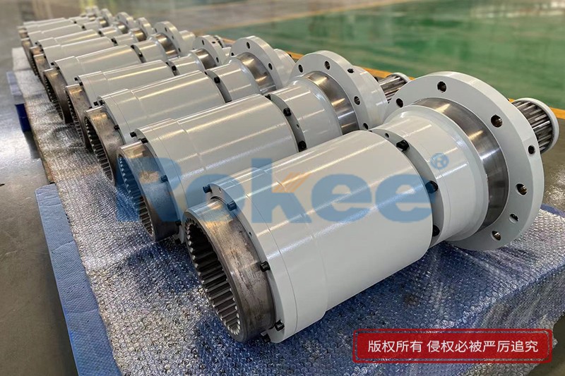
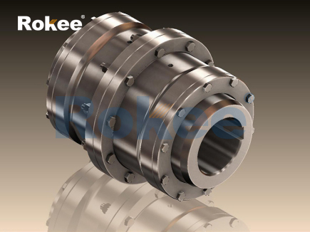
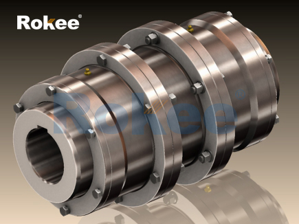
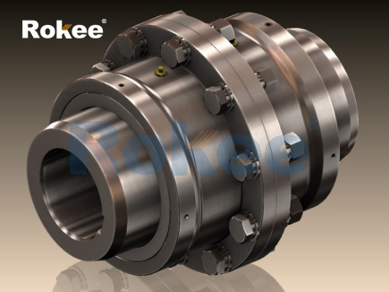
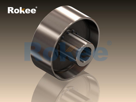
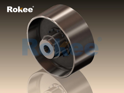
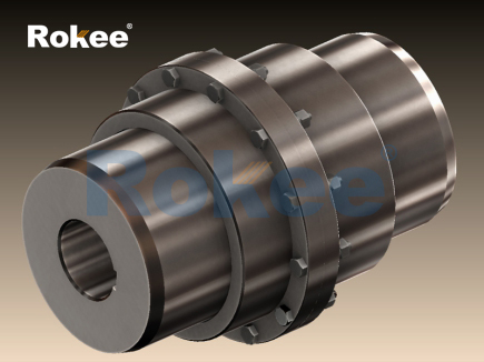
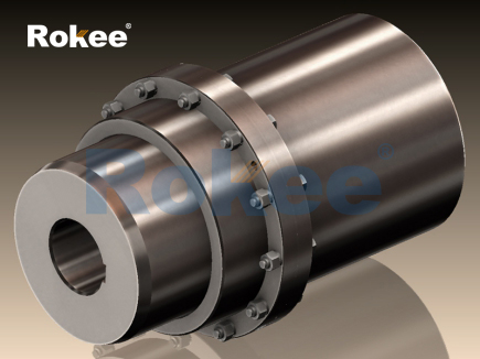
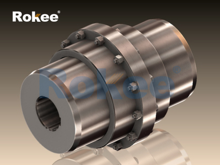
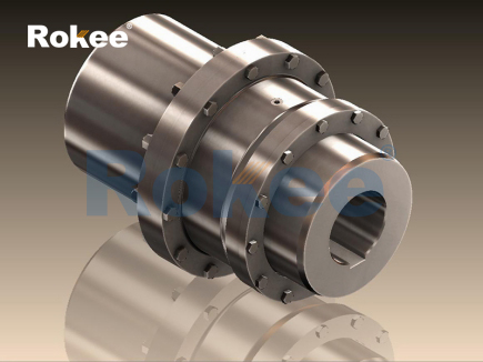
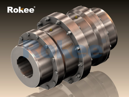
The full gear coupling serves as a mechanical connection component used to transmit torque between two rotating shafts, relying on the meshing of internal and external gear teeth to realize power transfer. Its basic structure consists of two hubs with external gear teeth and one sleeve equipped with internal gear teeth, where the external gear teeth on each hub engage with the internal gear teeth inside the shared sleeve. Unlike rigid shaft connections that demand precise alignment, the curved tooth profile of the gear teeth allows a certain range of relative displacement between the connected shafts, including angular misalignment, radial offset and axial movement. When the driving shaft rotates, torque passes through the external gear teeth of the driving hub to the internal gear teeth of the sleeve, and then transfers to the external gear teeth of the driven hub to drive the load shaft to rotate synchronously. The contact between gear tooth surfaces generates sliding and rolling friction during operation, which makes lubrication a fundamental requirement for stable operation. Without adequate lubricant filling inside the enclosed cavity of the coupling, direct metal-to-metal contact will cause rapid wear of tooth surfaces, increase vibration and noise, and shorten the usable service life. The closed housing design helps retain lubricating grease or oil and blocks dust, moisture and particulate impurities from entering the meshing zone, preventing abrasive damage to the gear teeth. This working mechanism makes the coupling capable of handling heavy torque loads while accommodating unavoidable shaft misalignment that arises from assembly tolerance, thermal expansion and mechanical deformation of connected equipment.
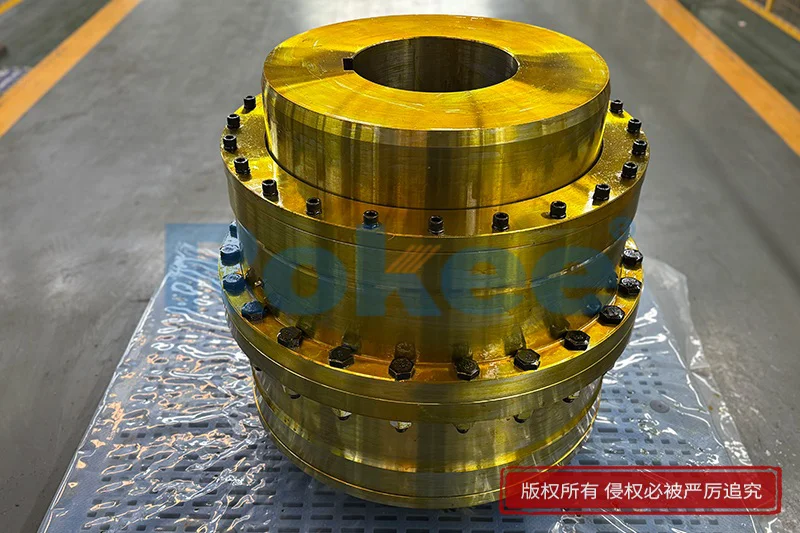
Load distribution on gear tooth surfaces is a core factor affecting the working performance of full gear couplings. Under ideal perfectly aligned operating conditions, the load spreads evenly across the full width of each meshed gear tooth, and stress concentration stays at a low level. In practical industrial operation, perfect alignment can hardly be maintained permanently, so relative displacement between shafts creates tilting contact between internal and external gear teeth. The curved tooth profile is specially designed to adjust the contact line automatically when misalignment exists, so the contact area shifts rather than concentrating on a tiny edge of the gear tooth. This design reduces peak contact stress and avoids premature chipping or cracking at tooth edges. When torque fluctuates, impact loads transmit instantly through the meshing gear pairs. The elastic micro-deformation of gear teeth can absorb part of instantaneous impact energy and buffer sudden load changes to some extent. However, excessive torque beyond the designed capacity will lead to plastic deformation of tooth surfaces, permanent tooth bending damage or complete tooth fracture. The magnitude of load also influences the thickness of the lubrication film between tooth surfaces. Heavy loads tend to squeeze the lubricant away from contact points, breaking the oil film and triggering boundary lubrication or dry friction, which accelerates surface pitting and wear. Operators need to match the coupling’s load capacity with the actual working torque and take periodic inspections to track tooth surface condition and lubricant quality for sustained reliable performance.
Misalignment compensation represents one of the most valuable functional characteristics derived from the working principle of full gear couplings. Three primary forms of shaft misalignment can be absorbed simultaneously within the allowable working range. Angular misalignment appears when the center lines of the two connected shafts intersect at a small angle, radial misalignment occurs when shaft center lines run parallel but separated by a distance, and axial misalignment refers to the relative movement of shafts along the rotation axis. The flexible meshing between internal and external curved gear teeth enables the hubs to tilt, shift and slide slightly relative to the sleeve during rotation. This compensation capability removes the need for ultra-precise shaft alignment during installation and offsets alignment changes produced by thermal expansion of casings, foundation settlement and component wear over running time. It is critical to understand that the coupling only tolerates misalignment within its designed limit. If misalignment exceeds the permitted range, the contact area of gear teeth becomes severely restricted, friction rises sharply, and cyclic bending stress repeatedly acts on the tooth roots. Long-term operation under excessive misalignment will generate continuous vibration, heat buildup and accelerated tooth fatigue damage. Even within acceptable misalignment values, larger offset will increase friction loss between gear teeth and raise the operating temperature of the coupling cavity. Proper alignment adjustment before commissioning remains essential to reduce unnecessary wear and extend the service cycle of the gear meshing pairs.
Power transmission efficiency of full gear couplings is closely tied to the friction state inside the gear meshing zone. Torque transfer happens through surface contact force between gear teeth, and relative sliding motion inevitably occurs between mating tooth surfaces while compensating shaft misalignment. This sliding action creates frictional resistance that consumes a small portion of input power and converts mechanical energy into heat. Under well-lubricated and properly aligned working conditions, the power loss stays relatively low, maintaining high transmission efficiency for continuous rotation. The lubricant forms a thin separating film between metal tooth surfaces, minimizing direct metal contact and cutting friction coefficient. Different lubricant types and viscosity grades affect the stability of the lubrication film. Lubricants with insufficient viscosity fail to sustain the protective film under heavy load or high temperature, while overly viscous lubricants increase viscous drag and raise power consumption. Heat generated from friction accumulates inside the enclosed coupling sleeve. If heat cannot dissipate effectively, the internal temperature rises, lubricant degrades, and the protective film breaks down. Degraded lubricant loses anti-wear properties and may form carbon deposits that stick to gear tooth surfaces, disrupting smooth meshing and worsening vibration. Regular replacement of lubricant and monitoring of operating temperature help preserve transmission efficiency and prevent thermal-induced damage to gear components.
Vibration and dynamic behavior during rotation are important reflections of the working state of full gear couplings. When rotating at a steady speed with normal load and alignment, the meshing of internal and external gear teeth produces stable periodic contact force, and the vibration level remains controlled. The coupling’s ability to accommodate misalignment reduces the transfer of mechanical vibration between the driving side and the driven side to a limited degree, yet it cannot fully isolate vibration like some elastic flexible couplings. Cyclic meshing of gear teeth generates inherent meshing vibration and noise, whose frequency correlates with rotating speed and gear tooth quantity. Abnormal operating conditions will amplify vibration signals. For example, partial tooth wear, pitting corrosion or uneven lubricant distribution causes irregular contact force during each rotation cycle, leading to increased vibration amplitude and irregular noise. Severe vibration can propagate to bearing systems of connected equipment, accelerate bearing fatigue and loosen fastening structures. In some cases, loose assembly between hubs and shafts also creates additional dynamic load that acts on gear teeth. Dynamic load cycles continuously apply tensile and compressive stress to gear tooth roots, gradually inducing fatigue cracks after long-term operation. Continuous vibration monitoring can capture early signs of gear tooth deterioration, allowing maintenance actions to be arranged before sudden coupling failure interrupts the whole mechanical system.
Material performance of gear components defines the durability and load-bearing capacity in the working principle of full gear couplings. Gear teeth on hubs and sleeves undergo repeated contact stress and bending stress in every rotation cycle. Suitable material selection ensures that gear teeth resist surface wear, contact fatigue and bending fatigue. The surface of gear teeth often needs enhanced treatment to improve surface hardness while maintaining sufficient toughness in the core material. Hardened tooth surfaces resist indentation and pitting under repeated contact pressure, and the tough core prevents brittle fracture under impact load. When the material hardness is insufficient, plastic flow can appear on tooth surfaces under heavy load, distorting the original curved tooth profile and weakening the misalignment compensation ability. On the contrary, materials that are too brittle may crack rapidly once local stress concentration occurs. Material properties also respond to temperature variation. High operating temperature reduces material hardness and accelerates fatigue development, while low temperature may increase brittleness and raise the risk of crack expansion. Corrosion from moisture or chemical contaminants can erode gear tooth surfaces, creating pits that become stress concentration points. The enclosed structure helps protect gear materials from corrosive media, but degraded lubricant may contain acidic substances that slowly corrode metal surfaces. Matching material characteristics with the working environment and load type guarantees stable meshing performance throughout the service life of the coupling.
Failure modes of full gear couplings derive directly from the stress and friction conditions formed in its gear meshing working principle. Surface pitting is one common failure form. Repeated contact stress on tooth surfaces generates tiny fatigue cracks beneath the surface. As rotation continues, lubricant penetrates these cracks, and hydraulic pressure formed inside cracks causes material flakes to peel off, leaving pits on tooth surfaces. Pitting gradually expands, damaging the smooth tooth profile, increasing vibration and noise. Tooth breakage happens when bending stress at tooth roots exceeds the fatigue limit, usually triggered by overload, excessive misalignment or deep fatigue cracks. Abrasive wear takes place when hard particles contaminate the lubricant, scratching and removing material from tooth surfaces and thinning gear teeth over time. Adhesive wear occurs when the lubrication film fails, causing metal adhesion between contact surfaces; parts of material tear off from one tooth and transfer to the mating surface. In some cases, lubricant aging and high temperature lead to thermal damage of tooth surfaces. Most failure processes develop slowly rather than instantly. Early-stage signs include rising operating temperature, increased noise and abnormal vibration. Understanding these failure modes helps design reasonable maintenance plans. Maintenance mainly focuses on lubricant renewal, visual inspection of gear condition and realignment of shafts, which can effectively delay the emergence and expansion of gear damage and avoid unexpected equipment shutdown.
Application scope and operational limitations complete the overall understanding of the working principle of full gear couplings. This type of coupling is widely used in mechanical systems that require high torque transmission and allow moderate shaft misalignment. It works well under continuous rotation conditions, adapting to steady load or moderate cyclic load. Its compact structure transmits large torque within a relatively small installation space compared with many other flexible couplings. However, the working principle also brings inherent limitations. The sliding friction between gear teeth means it is not suitable for applications demanding zero backlash, because clearance between meshing gear teeth exists inevitably. It also cannot absorb torsional vibration as effectively as couplings with elastic polymer elements. The enclosed lubrication system requires regular maintenance work, and running without lubrication will quickly destroy the gear meshing pairs. The coupling performs best under constant rotating direction. Frequent forward and reverse rotation introduces alternating impact load on gear teeth and speeds up fatigue damage. When selecting and deploying the coupling, engineers need to evaluate the actual working conditions including load characteristics, rotation speed, shaft misalignment level and ambient environment. Recognizing both the advantages and restrictions rooted in its gear meshing mechanism helps make proper use of the coupling, maintain stable power transmission and reduce the risk of unplanned mechanical downtime in various rotating equipment systems.
- Tags:
- Full Gear Couplings ,
- sandwich panel line ,
- sandwich panel machine
- pu sandwich panel machine
« Working Principle of Full Gear Couplings » Latest Update Date: Oct 20, 2026
https://www.rokeecoupling.net/blog/working-principle-of-full-gear-couplings.html