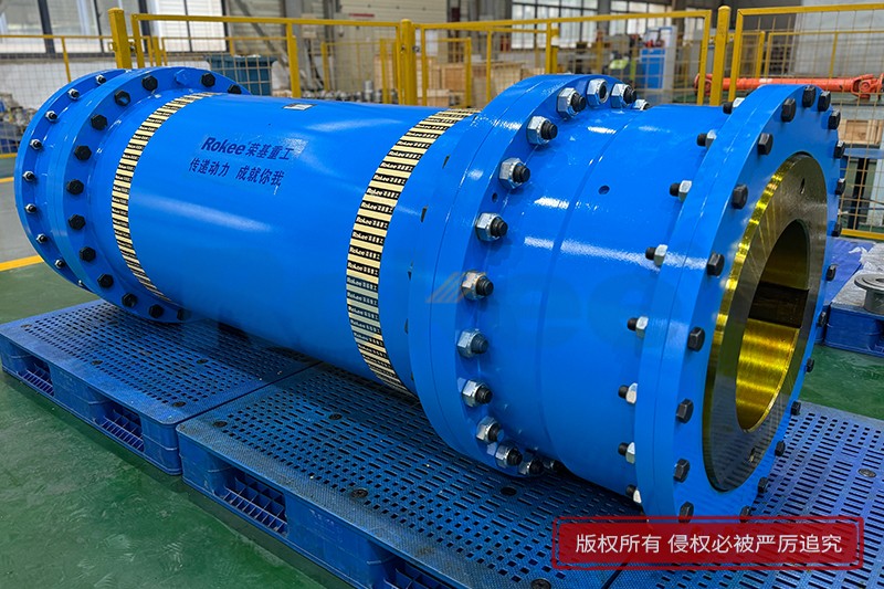
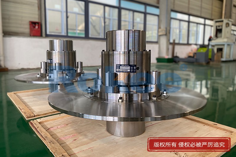
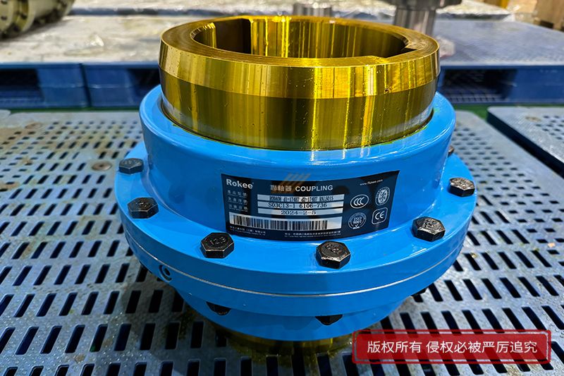
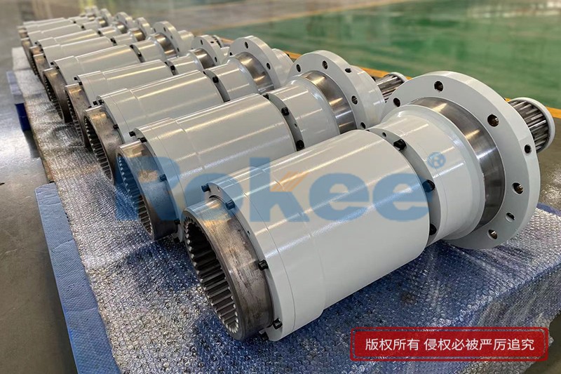
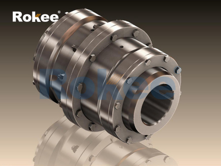
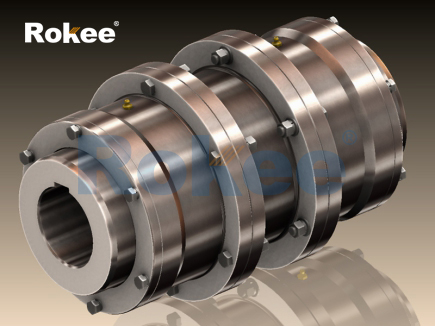
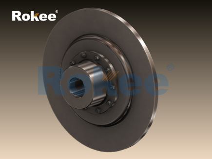
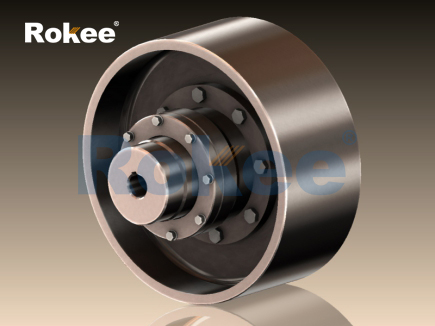
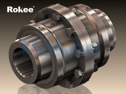
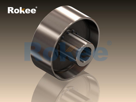
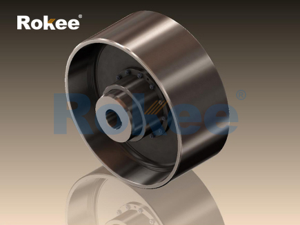
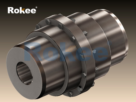
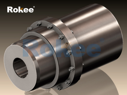
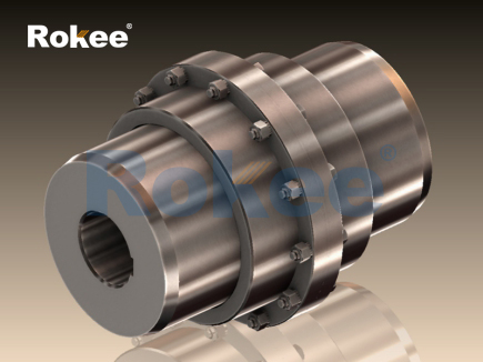
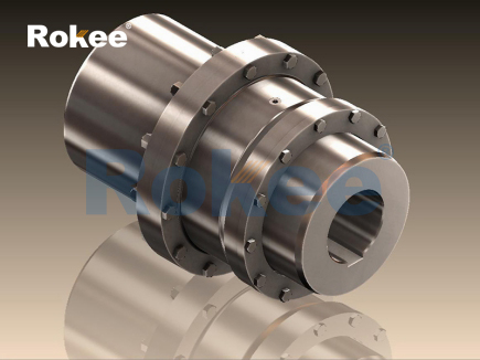
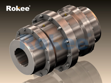
Brake drum gear couplings represent a specialized category of mechanical transmission components that integrate torque transmission and braking functions into a single compact assembly. At the core of their design lies the meshing connection between internal and external gear teeth, which serves as the primary medium for transferring rotational power between two connected shafts. The outer component, commonly referred to as the sleeve, carries internal gear profiles, while the hub mounted on the drive or driven shaft is fitted with external gear teeth that slide into the sleeve. Each tooth is manufactured with a slight crowning modification on its surface, allowing limited angular, radial and axial misalignment between the paired shafts during operation. Unlike rigid couplings that cannot tolerate any shaft offset, this gear engagement structure absorbs minor positional deviations generated by thermal expansion, assembly errors or long-term structural deformation of equipment. Attached to the outer sleeve is an integrated brake drum structure, which rotates synchronously with the gear sleeve when the coupling is in normal transmission status. This drum surface provides a smooth cylindrical friction working face for external brake assemblies. During normal running conditions, the whole coupling assembly spins together as a unified rotating unit, transmitting torque steadily while the brake components remain separated from the drum surface without generating friction resistance. The combination of gear transmission and brake drum eliminates the need to arrange separate braking and shaft connection parts side by side, saving valuable installation space on power transmission systems. This fundamental structural layout lays the foundation for the dual functional characteristics that distinguish brake drum gear couplings from ordinary gear couplings and standalone brake drums.
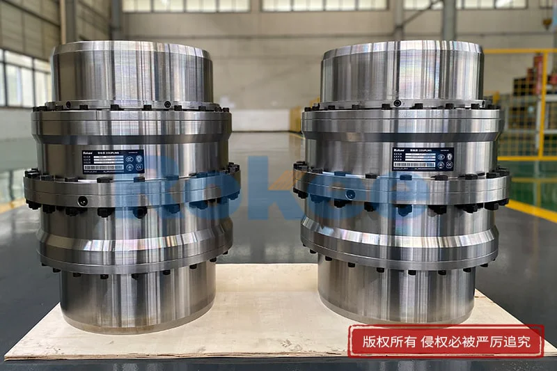
The gear meshing mechanism determines the torque carrying performance of brake drum gear couplings under continuous and fluctuating load conditions. When power input drives one shaft hub to rotate, the force is passed through the contact surfaces of external gear teeth to the internal gear sleeve, and then transferred onward to the second hub and the connected load shaft. The curved tooth contact distributes applied load across multiple tooth surfaces instead of concentrating stress on a small contact area, which improves the ability to withstand shock loads and transient torque spikes that frequently occur during equipment startup and sudden load changes. Lubrication plays an indispensable role within the gear meshing zone. A sealed cavity formed between the two hubs and the sleeve stores lubricant to reduce sliding friction between gear tooth surfaces, lower wear rate and dissipate heat produced by repeated tooth contact. The sealing structure prevents lubricant leakage and stops external dust, moisture and abrasive particles from entering the gear engagement area. If contaminants penetrate the seal, they will scratch tooth surfaces, accelerate wear and eventually lead to tooth surface pitting or material peeling. The tooth profile design permits controlled sliding motion between mating gears when shaft misalignment exists. This sliding action relieves additional bending stress that would otherwise build up on connected shafts and bearings. However, excessive misalignment will increase sliding friction on gear teeth, raise operating temperature and shorten the usable service life of the coupling. Operators must maintain alignment within the designed range to keep the gear meshing working state stable and consistent over long operation cycles.
The integrated brake drum works in coordination with external brake units to realize controlled deceleration and static holding of rotating machinery. The brake drum is machined as a continuous cylindrical surface on the outer circumference of the gear sleeve, rotating at the same rotational speed as the gear assembly. When the system needs braking action, brake shoes or friction linings mounted on the stationary brake frame press firmly against the outer cylindrical surface of the drum. Friction force generated between lining material and drum surface creates a resisting torque that counteracts the rotational torque transmitted by the coupling. This resisting torque slows down the rotation speed of the gear sleeve, the gear hubs and the connected shafts, until the whole rotating system stops completely. After braking completes, friction linings retract away from the drum surface to eliminate drag friction and avoid unnecessary power loss during normal operation. Since the drum is directly fixed to the torque-transmitting sleeve, the braking force acts on the rotating mass of the coupling itself together with the load equipment. This arrangement shortens the force transmission path for braking, delivering rapid response when braking commands are activated. Heat is inevitably produced on the drum surface during repeated braking cycles due to friction conversion of kinetic energy into thermal energy. The thick wall of the drum helps store and gradually dissipate this heat to surrounding air. Continuous heavy braking can cause substantial temperature rise on the drum surface, which may affect the mechanical property of drum material and influence the friction coefficient of contact linings if heat accumulates beyond acceptable levels.
The coordination between gear transmission section and brake drum requires careful consideration of dynamic interaction during transition between running and braking states. In normal power transmission mode, the gear pair bears the full operational torque while the brake drum simply rotates passively without contact. Once braking starts, friction torque acts on the sleeve first, and this resistance is transferred through the engaged gear teeth to both shaft hubs. At this moment, the gear teeth need to simultaneously carry original transmission torque and additional braking torque. Sudden emergency braking events create instantaneous peak loads on the gear tooth surfaces. The gear tooth structure must have sufficient strength to endure these combined loads without permanent deformation or fracture. The mass of the brake drum adds to the total rotating inertia of the coupling assembly. Larger drum dimensions enhance heat capacity for heavy-duty braking scenarios, yet they also increase inertia, requiring greater braking force to achieve the required deceleration rate. Designers balance thermal capacity and inertia according to the working cycle of target equipment. Vibration also arises during the transition process. The crowned gear teeth can dampen minor vibration caused by slight misalignment, but violent shock during emergency braking may excite vibration across the whole transmission chain. Proper balancing treatment on the entire rotating coupling assembly reduces vibration amplitude at high rotational speeds. Unbalanced rotating mass will generate cyclic centrifugal force, bringing extra load to supporting bearings and increasing noise level during both normal operation and braking procedures.
Installation and alignment directly affect the operating condition and service life of brake drum gear couplings, combining requirements for gear coupling assembly and brake drum positioning. During installation, the two shaft hubs are fixed onto the drive and driven shafts respectively, and the sleeve with integrated brake drum is assembled to cover the pair of gear teeth. Axial spacing between hubs must be adjusted accurately to reserve enough room for thermal expansion of shafts and coupling components. Improper axial clearance can cause the gear teeth to bind tightly or disengage partially under temperature changes. Shaft alignment checks cover radial offset, angular deviation and axial displacement. Any misalignment beyond the allowable range amplifies gear tooth sliding friction and accelerates wear. Meanwhile, the outer cylindrical surface of the brake drum must maintain good concentricity relative to the shaft centerline. If the drum runs eccentrically, the gap between brake linings and drum surface will vary periodically during rotation. This uneven gap leads to inconsistent friction force, pulsating braking torque, local overheating of the drum and abnormal vibration when brakes are applied. After positioning the coupling, sealing parts are fitted to enclose the gear chamber and lubricant is injected into the internal cavity. Post-installation inspection includes verifying free rotation of the whole assembly without jamming and checking that brake linings maintain uniform clearance around the drum circumference. Correct installation ensures both reliable torque transfer and stable braking performance throughout operation.
Wear and failure modes of brake drum gear couplings occur separately on the gear transmission part and the friction braking part, though degradation in one section can negatively impact the other. For the gear meshing area, the most common forms of deterioration include tooth surface abrasion, pitting, scoring and fatigue cracking. Abrasion develops when hard foreign particles contaminate the lubricant, gradually removing material from tooth contact surfaces. Pitting originates from repeated contact stress cycles that create tiny surface cracks, which expand and cause small metal flakes to detach from gear teeth. Insufficient lubrication sharply speeds up all these wear types and may even lead to direct metal-to-metal seizure between mating gears. For the brake drum, long-term friction contact with linings creates uniform wear on the outer cylindrical surface. Under severe braking conditions, localized thermal stress can generate surface cracks or thermal deformation of the drum. Deep grooves on the drum surface, caused by embedded hard debris in friction linings, disturb contact uniformity and reduce braking stability. Wear of the brake drum changes its dimensional tolerance and concentricity, which introduces extra load on the gear assembly. In turn, excessive gear wear creates shaft vibration that makes drum friction contact unstable. Regular inspection targets both components: technicians check gear tooth condition through access ports, monitor lubricant quality, and measure drum diameter and surface roughness. Timely maintenance replaces degraded lubricant, repairs friction surfaces or renews worn parts before minor defects progress into catastrophic equipment failure.
Lubrication and thermal management constitute two critical supporting systems that keep brake drum gear couplings working reliably under variable load cycles. The gear tooth meshing zone relies on lubricant to form a thin protective oil film between contact surfaces. This oil film separates metal surfaces, reduces friction loss, carries away friction heat and captures fine wear debris generated during gear engagement. Lubricant performance degrades over time due to thermal aging, oxidation and contamination. Degraded lubricant loses its ability to form stable oil films, which triggers accelerated gear wear. The sealed gear chamber slows lubricant aging and reduces contamination ingress, but periodic draining and refilling remain necessary. Thermal management has two independent sources of heat within the coupling. Heat from gear meshing is taken away mainly by circulating lubricant inside the sleeve. Heat from braking friction accumulates on the outer drum surface and dissipates primarily by convection to surrounding air. During frequent braking cycles, drum temperature rises rapidly. High drum heat can transfer inward through the sleeve wall and raise the temperature of lubricant stored in the gear cavity. Elevated lubricant temperature accelerates oil oxidation and reduces viscosity, weakening its lubricating effect. In heavy-duty applications, designers may optimize drum wall thickness and surface geometry to improve heat dissipation. Operators arrange working cycles to avoid continuous repeated braking that leads to excessive heat buildup, protecting both the friction drum and internal gear transmission system from thermal damage.
Application characteristics of brake drum gear couplings make them suitable for transmission systems that require both torque transmission and reliable mechanical braking in limited installation space. This integrated structure removes the need to mount a separate coupling and a separate brake drum in series along the shaft line, shortening the total length of the power train. This advantage is valuable for equipment where axial space is restricted. The gear connection provides high torque density, enabling the coupling to transmit large rotational force while accommodating controlled shaft misalignment. The brake drum integrated on the sleeve matches standard external brake structures, allowing flexible matching with different brake assemblies according to braking torque requirements. Typical working scenarios involve equipment that needs frequent startup, load variation and controlled stopping, where stable torque transfer and dependable braking must function together. Nevertheless, this type of coupling also carries inherent limitations. The rotating drum adds inertia, which increases energy consumption during acceleration and places higher demands on braking systems. Heat generated during braking can affect the internal gear lubrication environment, so continuous high-frequency braking applications need thorough thermal evaluation. Maintenance tasks require inspection of both gear components and brake friction surfaces, which increases the scope of routine maintenance compared to simple gear couplings. When selected and maintained appropriately, brake drum gear couplings deliver stable combined transmission and braking functions, serving as a practical solution for many rotating machinery systems that need compact, robust power connection with integrated braking capability.
- Tags:
- Brake Drum Gear Couplings ,
- sandwich panel line ,
- sandwich panel machine
- pu sandwich panel machine
« Working Principle of Brake Drum Gear Couplings » Latest Update Date: Oct 20, 2026
https://www.rokeecoupling.net/blog/working-principle-of-brake-drum-gear-couplings.html