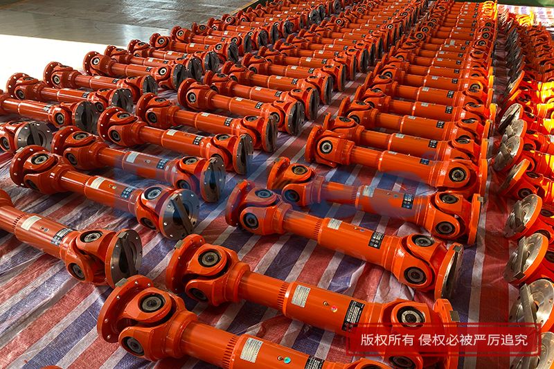
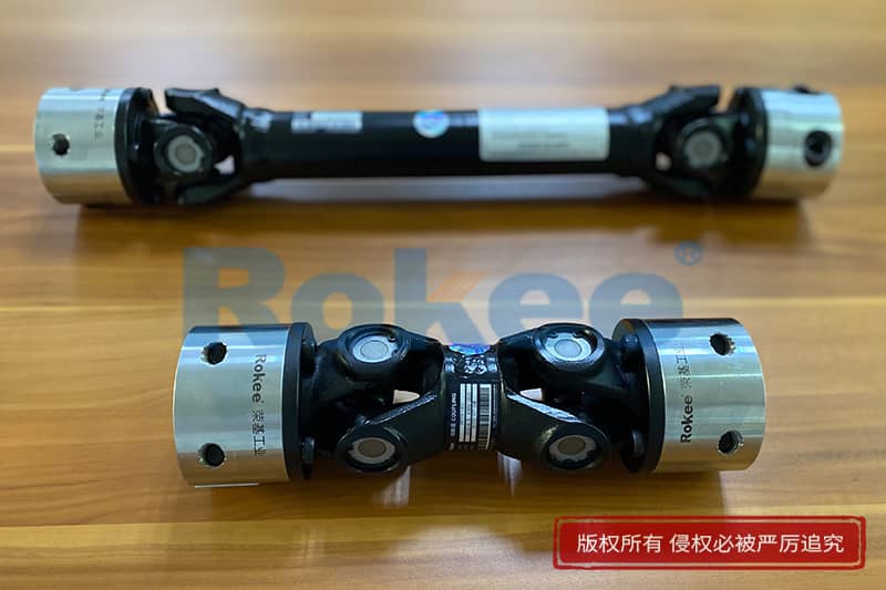
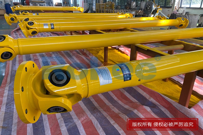
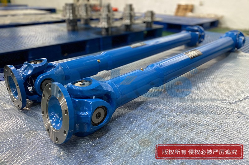
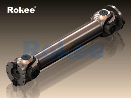
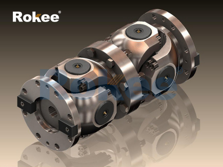
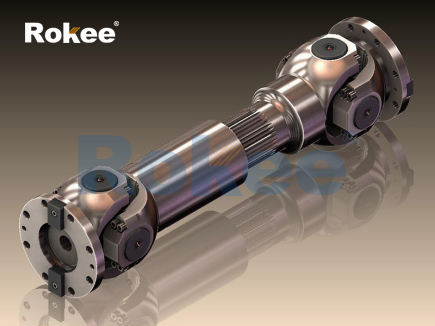
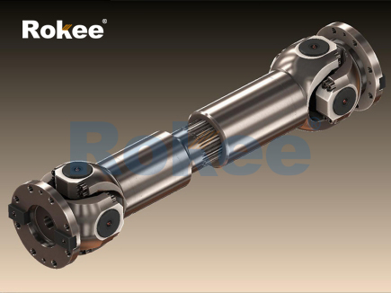
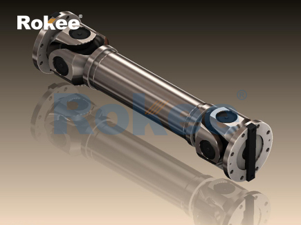
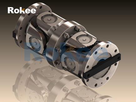
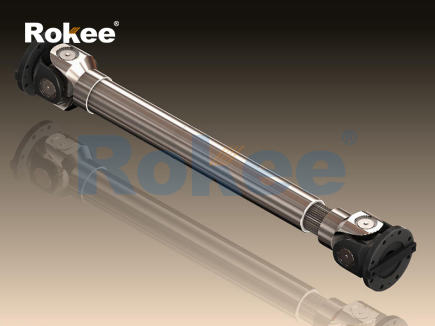
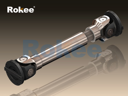
The cardan shaft, also widely known as the universal joint shaft, serves as a mechanical transmission component designed to transfer rotational torque between two shafts that are not perfectly aligned along a single central axis. Its core structure relies on universal joints, cross-shaped bearing assemblies that connect shaft segments and allow for angular displacement during operation. When the driving shaft rotates, the cross piece within the joint transfers rotary force to the driven shaft even when the two shafts form an inclined angle. This angular flexibility distinguishes the cardan shaft from rigid solid shafts, which can only transmit power reliably when shafts remain coaxial. Small misalignments emerge constantly in many mechanical systems due to vibration, thermal expansion, minor assembly tolerances, or slight structural deformation. Without a flexible transmission element like the cardan shaft, these deviations would create excessive bending stress on rigid shafts, leading to rapid wear, bearing damage, or sudden mechanical failure. The basic working cycle begins as torque enters the first universal joint, where the cross bearing pivots to accommodate the shaft angle, then the force passes through an intermediate tubular shaft section before reaching the second universal joint, which further adjusts the angle to deliver torque to the output side. While rotation proceeds smoothly at a steady average speed, a single universal joint produces fluctuating instantaneous rotational speed at non-zero angles, a natural mechanical characteristic that must be managed through paired joint arrangements in practical designs.

The fluctuation in instantaneous speed generated by a single universal joint represents one of the most fundamental properties governing cardan shaft operation. If only one universal joint connects two angled shafts, the driven shaft will accelerate and decelerate twice for every full rotation of the driving shaft. This periodic variation does not alter the overall number of rotations completed over time, yet it introduces cyclic torsional vibration across the whole transmission system. The magnitude of this speed fluctuation grows as the working angle between connected shafts increases, creating greater vibration and dynamic loads on bearings, gears, and other linked machine parts. To counteract this unwanted effect, most functional cardan shaft assemblies employ two universal joints arranged in sequence. The two joints are positioned so that the speed variation produced by the first joint is offset by an equal and opposite speed variation from the second joint. This balancing condition requires careful orientation of the joint yokes: the yokes on the intermediate shaft must lie in the same plane. When this geometric requirement is met, the final output shaft maintains a nearly constant instantaneous rotational speed matching the input shaft, eliminating the cyclic speed oscillation that occurs with a single joint. Engineers must account for this alignment rule during installation, because improper yoke positioning will amplify vibration instead of cancelling it, shortening component service life significantly.
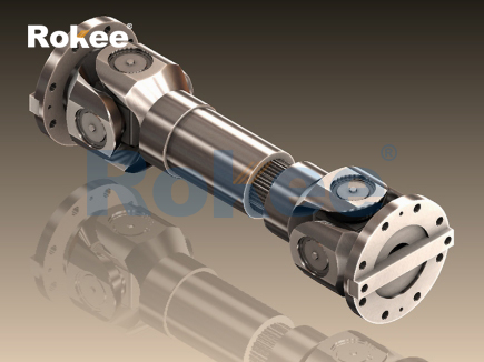
The intermediate shaft section forms the central body of the cardan shaft assembly and performs dual functions of torque transmission and length adjustment. This segment is commonly constructed as a hollow tubular structure rather than a solid bar. Hollow tubing provides high torsional stiffness with reduced overall mass, cutting down rotational inertia during high-speed operation and lowering the centrifugal forces acting on the universal joints. Many intermediate shafts include a sliding spline connection between two tubular parts. The spline consists of matching external and internal gear-like profiles that slide along the axial direction while continuing to transmit torque. This sliding mechanism compensates for changes in the distance between the driving and driven equipment that occur during operation. Such length changes can arise from movement of machine components, suspension deflection in mobile machinery, thermal contraction and expansion of metal parts, or shifting loads that alter the spacing between connection points. The spline slides freely within a defined range to absorb axial displacement without disrupting power transfer. Lubrication is critical for the spline surface; insufficient lubrication leads to metal-on-metal friction, galling, and accelerated wear of the spline teeth, which can eventually cause backlash and torque loss during load transitions. The combined design of hollow tube and sliding spline gives the cardan shaft the ability to handle both angular misalignment and axial displacement simultaneously.
Bearing assemblies inside each universal joint are the key moving elements that permit angular rotation and load transfer in the cardan shaft. The cross-shaped spider sits between four needle roller bearings fitted into the bores of the joint yokes. Needle rollers offer a large contact surface within a compact space, distributing torque loads evenly while maintaining low friction during pivoting motion. As the shaft rotates and the working angle remains present, the needle bearings spin continuously to accommodate the swinging movement of the spider relative to the yoke. Each bearing is sealed to retain grease and block dust, moisture, and abrasive particles from entering the contact zone. Contamination inside the bearing will scratch roller surfaces and create wear debris, which accelerates fatigue and can lead to bearing seizure. The bearings carry both radial loads from rotation and impact loads created by sudden changes in transmitted torque. Under heavy shock loading, local contact stress on the bearing surfaces rises sharply, increasing the risk of surface fatigue cracks. Regular lubrication replenishes the protective grease layer, reduces friction heat, and prevents corrosion of the bearing and spider surfaces. When bearings degrade, the joint develops play and vibration, which propagates through the entire shaft assembly and damages adjacent mechanical components.
Vibration and dynamic load behaviour are essential considerations for understanding real-world cardan shaft working performance. Even when two universal joints are properly phased to cancel speed fluctuations, dynamic forces still arise from mass imbalance, residual misalignment, and torque transients. Every rotating component has a centre of mass, and any offset between this centre and the rotational axis generates centrifugal force. As operating speed rises, centrifugal forces increase rapidly, creating bending vibration that shakes the shaft and connected structures. Manufacturers balance cardan shaft assemblies to minimise mass offset, but operational wear, denting of the tube, or deformation can degrade balance over time. Torsional vibration also occurs when transmitted torque fluctuates, such as during start-up, load impact, or variable power output. These torsional oscillations can resonate with the natural frequency of the shaft system, producing large amplitude stress that may cause fatigue fractures. Operating speed limits are defined to avoid approaching critical resonant speeds. Operators must observe these limits, because running near resonance can quickly destroy the shaft assembly. Additional dynamic loads come from angular acceleration, especially when machinery starts or stops, placing sudden shock loads on universal joints and spline sections.
Material selection and mechanical fatigue govern the long-term reliability of cardan shafts under cyclic loading. All parts of the shaft experience repeated mechanical stress with every rotation. The spider, yokes, tube, and spline teeth undergo cycles of tension, compression, and shear stress. Over countless rotation cycles, microscopic cracks can form at points of high stress concentration. These tiny cracks slowly expand under repeated load until the component fails. Materials used for the main structural parts are chosen for high strength, good toughness, and resistance to fatigue. Surface treatments are often applied to bearing races, spline surfaces, and spider journals to improve hardness and wear resistance. Hardened surfaces resist abrasion and surface fatigue, while the underlying material retains toughness to prevent brittle fracture under shock loads. High operating temperatures can weaken material properties, reduce grease effectiveness, and speed up fatigue development. Corrosion from humid or chemically active environments creates surface pits that act as starting points for fatigue cracks. Designers evaluate the expected load cycles, peak torque values, operating angles, and environmental conditions to size each component appropriately, ensuring the service life meets the demands of the application without premature breakage.
Installation and operating conditions directly affect how a cardan shaft functions and how long it remains in service. Correct alignment of yoke planes and control of the operating angle are primary installation requirements. The working angle must stay within the designed range; excessive angles amplify bearing sliding friction, raise heat generation, and increase cyclic loading on universal joints. The arrangement must also maintain suitable clearance for the sliding spline, ensuring the spline can move through its full travel range without bottoming out. During operation, the shaft should not contact nearby structures, as rubbing creates local heating and material loss. Regular inspection routines check for loose fasteners, seal damage, grease leakage, spline wear, and joint play. Damaged seals are one of the most common failure triggers, as they allow contaminants to enter the bearings. Overloading beyond the maximum torque rating causes permanent deformation of yokes, spiders or tubular sections, which ruins balance and structural integrity. Operating at low angles for extended periods can also create wear patterns different from those seen at larger angles. Operators need to recognise early warning signs such as unusual noise, vibration increases, or fluctuating power delivery, as these signals indicate progressive component degradation before catastrophic failure takes place.
Advancements in cardan shaft design continue to refine torque transmission performance while preserving the fundamental working principle of paired universal joints. Modern design approaches use computer simulation to model torsional vibration, stress distribution, and dynamic behaviour across different operating speeds and load profiles. These simulations help optimise tube geometry, joint dimensions, and spline design to reduce weight while maintaining strength. Improved sealing technologies extend bearing service life by offering better protection against harsh environmental conditions. Lubricant formulations have also advanced, providing stable performance across wider temperature ranges and resisting degradation under continuous shear inside moving joints. While the basic mechanism of angular torque transfer remains unchanged, refined manufacturing processes produce more consistent component geometry and better rotational balance. Despite these improvements, the core limitations still exist: cardan shafts cannot accommodate infinitely large angular deflections, they remain sensitive to overload, and wear is inevitable with continuous use. Understanding the underlying working principle helps designers, technicians, and operators select suitable configurations, maintain equipment properly, predict failure modes, and maximise the functional lifespan of cardan shaft assemblies across many different mechanical transmission applications.
- Tags:
- Cardan Shaft Couplings ,
- Industrial Cardan Shafts ,
- Cardan Shafts ,
- Cross Cardan Shafts ,
- sandwich panel line ,
- sandwich panel machine
- pu sandwich panel machine
« Working Principle of Cardan Shafts » Latest Update Date: Oct 20, 2026
https://www.rokeecoupling.net/blog/working-principle-of-cardan-shafts.html