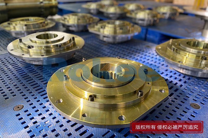
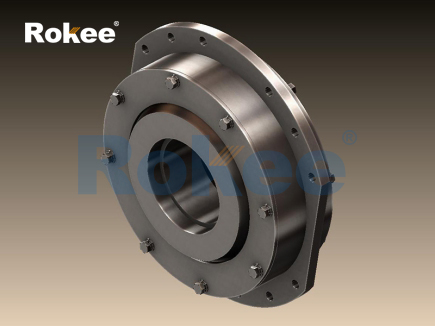
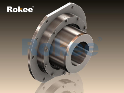
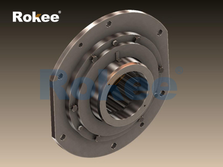
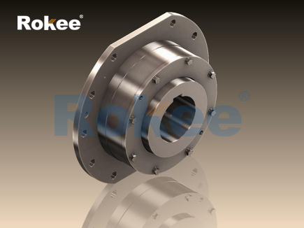
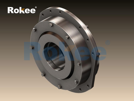
The drum coupling serves as a mechanical connecting component used to join two rotating shafts and transmit torque while accommodating minor misalignment between them. At the core of its structure are the hub elements fitted onto the ends of the driving and driven shafts, paired with a sleeve equipped with internal curved tooth profiles, which are often referred to as drum-shaped teeth. Unlike ordinary straight-tooth gear couplings where tooth surfaces engage along a narrow contact line, the outer teeth on the hubs are machined into a convex drum shape. This special geometric feature changes the contact condition between meshing teeth when the connected shafts are not perfectly aligned. When rotational power passes from the driving shaft to the driven shaft, torque transfers through the meshing interface between the drum-shaped outer teeth and the straight inner teeth of the sleeve. The curved tooth surface allows the contact zone to shift smoothly rather than concentrating stress on a single edge of the tooth. Even under slight angular, radial, or axial misalignment generated by installation errors, thermal expansion of equipment parts, or slight foundation deformation during operation, the teeth can slide and adjust their contact position without creating sharp stress peaks. This flexible engagement prevents the harmful bending loads that rigid couplings would impose on shaft bearings and seals. The basic working logic relies on controlled sliding contact between the modified tooth profiles instead of elastic deformation of rubber or polymer materials, making the coupling suitable for power transmission scenarios that require high torque capacity and stable performance under continuous rotation. The meshing teeth remain engaged at all times during rotation, ensuring uninterrupted torque transfer while the drum tooth geometry provides the necessary allowance for shaft displacement.

The geometric design of drum teeth directly determines how the coupling handles misalignment during operation. The outer teeth on each hub are processed with a crown, meaning the tooth profile curves outward along the tooth width direction. This crown or drum contour is not arbitrarily shaped; its curvature is calculated to limit the contact area shift within a safe range when the two connected shafts form a small angle. When angular misalignment exists between shafts, the meshing point between inner and outer teeth moves toward one end of the tooth width. For straight teeth, this shift would concentrate pressure on the tooth tip edge, leading to rapid wear, pitting, or tooth fracture. The drum profile distributes the contact pressure across a wider area of the tooth surface as the contact point moves. Radial misalignment creates a slight offset between the axis of the driving hub and the driven hub, and the curved tooth surface permits small relative radial sliding between the sleeve and hubs as rotation proceeds. Axial displacement caused by thermal elongation of shafts can also be absorbed through limited axial sliding of the drum teeth inside the sleeve bore. It is important to recognize that this coupling can only compensate for small magnitudes of misalignment. Excessive offset or angle will push the tooth contact beyond the designed range, creating heavy friction and accelerated tooth surface degradation. All relative movements between meshing surfaces are sliding motions, which makes lubrication an indispensable part of maintaining normal working conditions. Without proper lubricant filling in the tooth cavity, metal-to-metal friction will quickly raise surface temperature and wear away the precision machined tooth profiles, losing the ability to adjust misalignment effectively.
Torque transmission proceeds continuously through tooth meshing throughout the full rotation cycle of the drum coupling. As the driving shaft rotates, the hub fixed to it spins together, and its drum-shaped outer teeth push against the inner teeth of the connecting sleeve. The sleeve then transfers the rotational force to the outer teeth of the driven hub, and finally drives the driven shaft to rotate at the same speed. During each rotation, multiple tooth pairs stay in contact simultaneously to share the applied torque load. This shared load distribution reduces the stress borne by any single tooth and improves the overall load-carrying capacity compared with couplings that rely on fewer contact points. When the system experiences fluctuating torque, such as periodic load shocks from processing machinery, the meshing teeth absorb part of the transient load through slight micro-sliding on the curved surfaces. The sliding motion allows small relative movement between tooth pairs to buffer sudden torque spikes, though this buffering effect is much weaker than that of elastomeric couplings. The rotational speed remains synchronized between the driving and driven shafts under normal working conditions, because the teeth maintain positive engagement and cannot slip freely. Any speed difference between the two shafts only exists at the microscopic contact surface of the meshing teeth and does not affect the overall rotational synchronization of the transmission system. The direction of torque transfer can be reversed, so the coupling works equally well when rotation switches clockwise to counterclockwise. However, frequent torque reversal will increase the frequency of impact between tooth flanks, accelerating wear on both the inner and outer tooth surfaces and shortening the usable service life of the coupling assembly.
Friction and lubrication play a critical role in the stable operation of drum couplings, as relative sliding always occurs between the drum-shaped outer teeth and inner sleeve teeth during misaligned operation. The sliding action between metal tooth surfaces generates friction force and frictional heat. If dry contact occurs, high friction coefficients will produce excessive heat, which softens the surface layer of the metal teeth and causes abrasive wear and surface fatigue damage. Lubricant fills the gaps between meshing teeth, forming a thin protective oil film that separates the two metal surfaces. This film reduces friction coefficient, lowers heat generation, and prevents direct metal contact. The lubricant also carries away part of the heat generated by sliding friction and captures tiny wear particles produced during tooth meshing, keeping the tooth cavity clean. The sealing structure of the coupling keeps the lubricant sealed inside the tooth chamber and blocks external contaminants like dust, moisture, and fine debris from entering. Contamination in the lubricant will turn the fluid into an abrasive mixture, scratching the precision tooth surfaces and destroying the smooth drum profile. The viscosity and type of lubricant need to match the operating temperature and rotational speed of the equipment. At high rotating speeds, the lubricant must maintain sufficient film strength without creating excessive viscous resistance. When operating temperature rises, the lubricant gradually degrades, losing its ability to form stable oil film. Over time, the lubricant will need replacement to sustain the coupling’s working performance. Poor lubrication is one of the most common causes of early failure in drum couplings, even when the shafts are installed within the allowed misalignment range.
Dynamic load distribution under misaligned conditions further illustrates the unique working principle of drum couplings. When shafts are perfectly aligned, the contact pressure distributes evenly across the full width of each drum tooth. Once misalignment appears, the contact zone shifts, and the drum tooth curvature redistributes pressure automatically. The curved profile prevents edge loading, which would otherwise create localized high pressure points on straight gear teeth. The magnitude of dynamic load changes with rotation angle, because the direction of misalignment remains fixed relative to the foundation while the coupling rotates. This creates periodic variation in sliding distance and contact pressure during every full rotation. The periodic load fluctuation is usually small if misalignment stays within the designed limit, and the transmission system can tolerate such minor cyclic stress. If misalignment exceeds the designed allowance, the range of contact movement expands, cyclic stress increases sharply, and vibration levels of the whole machine rise noticeably. Excess vibration transfers extra loads to supporting bearings, shaft seals and other adjacent components, leading to premature damage outside the coupling itself. The drum tooth design works to contain this dynamic load variation. Unlike flexible couplings that deform elastically, this coupling adjusts load distribution through geometric sliding contact, so stiffness remains relatively high. The high torsional stiffness means the coupling does not introduce large torsional deflection under heavy torque, which suits applications requiring precise rotational angle control. At the same time, the stiffness will transmit vibration and shock more directly than elastomer couplings, which is a key characteristic determined by its metal tooth meshing working principle.
Thermal effects interact closely with the working state of drum couplings during long-duration operation. Continuous torque transmission and tooth sliding friction generate heat inside the enclosed tooth cavity. Temperature increase changes multiple physical conditions of the coupling assembly. Metal components expand when heated, which alters the clearance between meshing teeth and may introduce additional axial or radial displacement between shafts. Such thermally induced displacement is one of the main reasons that transmission systems require coupling misalignment compensation. The drum tooth structure accommodates this thermally produced movement through its sliding contact. Rising temperature also affects lubricant performance. High temperature accelerates lubricant oxidation, reduces oil film thickness, and may cause oil leakage through sealing elements. In systems with large temperature variation between startup and steady running, the coupling must handle the changing shaft position as equipment warms up. During cold startup, lubricant viscosity is higher, and sliding resistance between teeth is greater. As temperature rises, lubricant flows more easily and friction decreases, reaching a stable working state. If heat accumulates faster than it can dissipate, tooth surface temperature can reach levels that damage the surface hardening layer of the teeth. Surface hardening treatment on drum teeth improves wear resistance and contact fatigue strength, helping the tooth profile maintain its curved shape under repeated pressure and sliding. Any permanent deformation of the drum contour will undermine the coupling’s ability to compensate misalignment, and load concentration will appear again on the tooth edges. Proper heat management is therefore an essential supporting factor for the coupling’s core working principle of meshed curved tooth contact.
Failure modes of drum couplings can be traced back to the basic mechanism of tooth meshing and sliding contact, helping to verify and understand its working principle. The most typical failure occurs on the tooth contact surfaces. Long-term repeated contact stress leads to surface fatigue, creating pits on the curved tooth faces. Pitting develops when the oil film cannot fully separate metal surfaces, and cyclic pressure generates tiny cracks that expand and peel off material. Another common failure is abrasive wear, usually triggered by contaminated lubricant or insufficient lubrication. Wear gradually removes the curved drum profile, turning the outer teeth closer to straight geometry. Once the drum contour is worn away, the coupling loses its capability to redistribute contact pressure, and edge loading begins. Tooth fracture may happen when overload combines with existing tooth surface damage. Excessive torque applies stress beyond the material strength limit, and cracks originating from worn tooth surfaces propagate until the tooth breaks. Damage can also occur on sealing parts. Seal failure allows lubricant escape and pollutant ingress, starting a chain reaction of tooth wear. Many failures are not caused by the coupling itself but by excessive shaft misalignment imposed by installation drift or foundation settlement. When misalignment exceeds the designed range, the sliding motion between teeth becomes too large, friction and vibration rise continuously, and damage progresses rapidly. All these failure forms reflect that the drum coupling works reliably only when the curved tooth surfaces can maintain controlled sliding contact with adequate lubrication and limited misalignment. Any condition breaking this working condition will degrade or disable its function of torque transmission and displacement compensation.
Comparing drum couplings with other types of shaft couplings helps highlight the distinctive features of their working principle. Rigid couplings connect shafts firmly without any allowance for relative displacement, so they cannot absorb misalignment at all and transfer all bending loads directly to shaft bearings. Elastomeric couplings use deformation of polymer elements to accommodate misalignment. Their working mechanism depends on elastic stretching, compression or shearing of soft materials, which gives good vibration damping but limits torque capacity and operating temperature range. Gear couplings with straight teeth transmit torque through tooth meshing as well, yet they lack the curved drum tooth profile. Straight gear couplings can only tolerate very small misalignment before edge loading appears, restricting their practical use. Drum couplings adopt metal drum-shaped tooth meshing with sliding contact. This design combines high torque transmission capacity and the ability to compensate multiple forms of minor shaft misalignment. Its torsional stiffness is much higher than elastomer couplings, making it suitable for heavy-load and high-speed rotating equipment. The main drawback comes from the sliding metal contact, which requires continuous lubrication and sealing maintenance, a requirement that elastomeric couplings do not need. While elastomer parts can absorb shock and isolate vibration effectively, drum couplings transmit torsional vibration more directly. Therefore, selection depends on the priority of system requirements. When heavy torque transfer and misalignment accommodation are required and regular lubrication maintenance is acceptable, the drum coupling’s working principle delivers stable mechanical performance. The drum tooth profile remains the defining innovation that differentiates this coupling from other gear-type couplings and supports its function of reliable power transmission under imperfect shaft alignment.
- Tags:
- Brake Drum Couplings ,
- Drum Couplings ,
- sandwich panel line ,
- sandwich panel machine
- pu sandwich panel machine
« Working Principle of Drum Couplings » Latest Update Date: Oct 20, 2026
https://www.rokeecoupling.net/blog/working-principle-of-drum-couplings.html