In the modern mechanical transmission industry, mechanical components that realize power transmission under offset and angular deflection conditions occupy an indispensable core position in mechanical system design. As a typical universal transmission component, cardan couplings have been widely adopted in various mechanical equipment due to their unique structural adaptability and reliable power transmission performance. A three-dimensional digital model of cardan couplings serves as a fundamental technical carrier for mechanical analysis, structural optimization, production simulation and teaching demonstration, which can intuitively display the internal composition, motion logic and mechanical characteristics of the coupling. Compared with traditional two-dimensional engineering drawings, the 3D model breaks through the limitations of planar expression, realizes stereoscopic visualization of complex mechanical structures, and provides accurate data support for subsequent finite element analysis, motion simulation and structural improvement. With the continuous upgrading of digital manufacturing technology, the application value of cardan coupling 3D models in mechanical research, equipment manufacturing and engineering maintenance has become increasingly prominent, gradually becoming an essential technical tool in the whole life cycle management of coupling products.
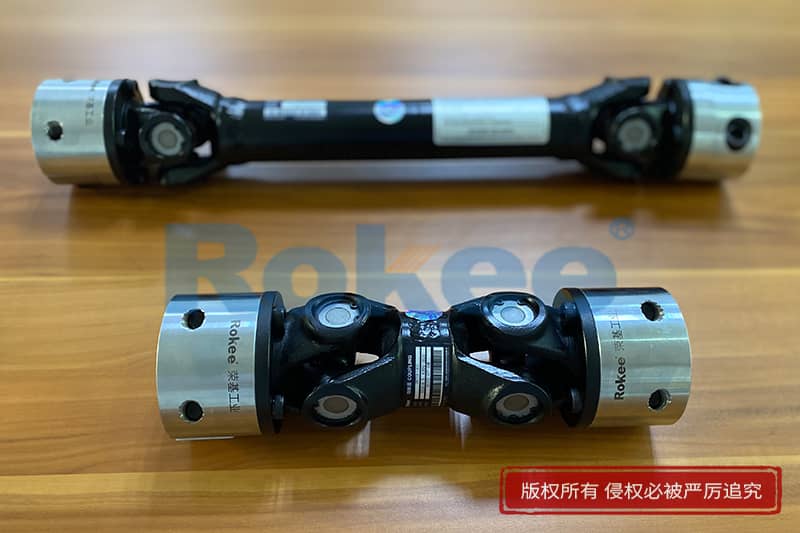
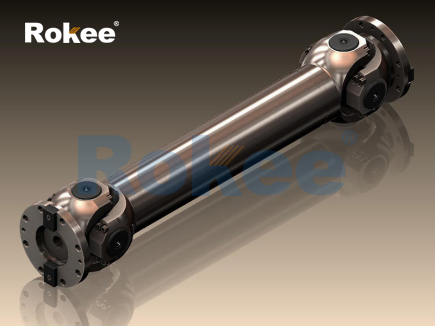
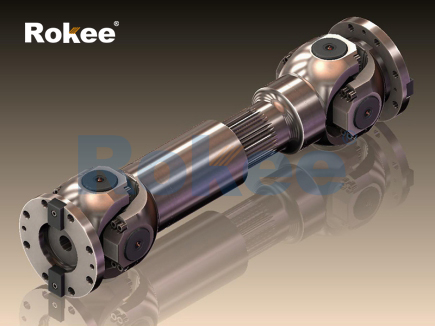
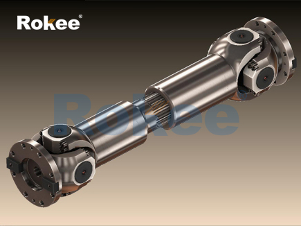
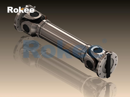
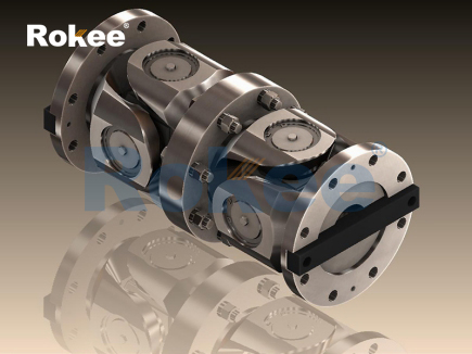
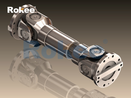
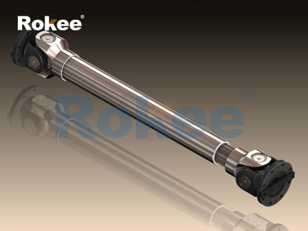
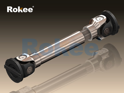
The basic structure of cardan couplings is highly concise and mechanical, and each component bears distinct functional responsibilities in the power transmission process. A standard cardan coupling is mainly composed of two yoke forks, a cross shaft, rotating pin shafts and connecting bearings, and all components cooperate closely to complete flexible power transmission. In the 3D modeling process, every structural detail needs to be accurately restored to ensure the consistency between the digital model and the physical prototype. The yoke forks are distributed at both ends of the coupling, with symmetrical fork-shaped structures that provide stable connecting points for the cross shaft. The cross shaft, as the core force-bearing component, adopts an integrated cross structure, and four sets of rotating matching structures are arranged at the end of each shaft section to connect with the yoke forks. The built-in bearings are installed at the matching positions of the cross shaft and the yoke forks, which can effectively reduce friction resistance during rotation and improve the flexibility of angular movement. The 3D model clearly presents the assembly relationship between components, including the clearance fit between pin shafts and bearing inner rings, the interference fit between bearing outer rings and yoke fork holes, and the symmetrical spatial distribution of the two end yoke forks. This detailed structural restoration enables researchers to clearly observe the spatial position changes of each part during the operation of the coupling, which is difficult to achieve through traditional planar drawings.
The construction of a high-precision 3D model of cardan couplings follows standardized mechanical modeling logic, covering multiple links such as parameter determination, component modeling, virtual assembly and model calibration. Before modeling, it is necessary to clarify the basic mechanical parameters of the coupling, including the maximum allowable deflection angle, rated transmission torque, shaft hole matching size and component material characteristics, which lay a parameter foundation for the establishment of digital models. In the single-component modeling stage, solid modeling technology is used to complete the structural design of yoke forks, cross shafts and pin shafts. For regular structures such as shaft bodies and through holes, basic stretching and rotating modeling commands are adopted; for fillets, chamfers and special transition structures at component joints, fine grinding is carried out to restore the processing technology of physical parts. In the virtual assembly link, constraint relations are set according to the actual assembly sequence, including fixed constraints between the shaft body and yoke forks, and rotating constraints between the cross shaft and yoke forks, so as to simulate the real assembly state of the coupling. After the initial model is completed, model calibration is required to eliminate redundant structural surfaces and unreasonable constraint relations, and detect the interference between components in the motion stroke, ensuring that the rotation and deflection movements of the 3D model are completely consistent with the physical coupling.
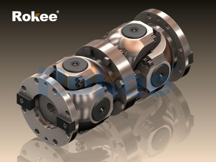
Motion characteristic analysis is one of the core application functions of the cardan coupling 3D model. A single cardan coupling has inherent non-uniform velocity transmission characteristics under angular deflection conditions. When there is an included angle between the driving shaft and the driven shaft, the angular velocity of the driven shaft will fluctuate periodically within a single rotation cycle, even if the driving shaft maintains a constant rotation speed. The 3D motion simulation system can visually display this velocity change law. By setting different deflection angle parameters in the model, the rotation state of the coupling under varying working conditions can be observed in real time. When the deflection angle increases, the fluctuation range of the driven shaft angular velocity will expand correspondingly, bringing periodic vibration and torque fluctuation to the transmission system. In order to optimize the transmission stability, the 3D model can also build a double cardan coupling combined structure. By adjusting the installation phase and deflection angle of the two single couplings, the velocity fluctuation generated by a single coupling can be offset mutually, realizing approximate constant velocity transmission. The intuitive motion demonstration of the 3D model helps mechanical researchers deeply understand the velocity transmission mechanism of cardan couplings and summarize the structural design rules for improving transmission stability.
Finite element simulation based on 3D models provides reliable mechanical data for the performance optimization of cardan couplings. In actual working conditions, the coupling needs to bear composite loads such as torsion, shear and impact, and the stress concentration phenomenon is prone to occur at the cross shaft journal, the root of the yoke fork and the pin shaft connection position. By importing the high-precision 3D model into finite element analysis software, a reasonable mesh division can be carried out for key force-bearing parts. After setting material attributes, load conditions and constraint boundaries, the stress distribution, strain deformation and fatigue damage risk points of the coupling under rated and extreme working conditions can be accurately calculated. The simulation results show that the stress concentration area of the cardan coupling is mainly concentrated at the transition fillet of the cross shaft journal. Excessive stress will lead to plastic deformation or fatigue fracture of the component during long-term operation. Relying on the visual data cloud picture of the 3D model, designers can optimize the local structure, such as increasing the fillet radius of the stress concentration area and thickening the wall thickness of the yoke fork, so as to reduce the internal stress peak value and improve the structural strength and service life of the coupling.
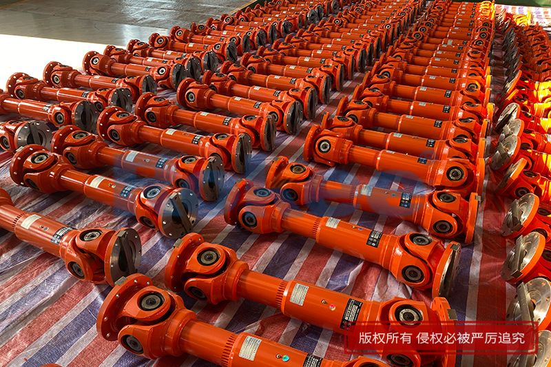
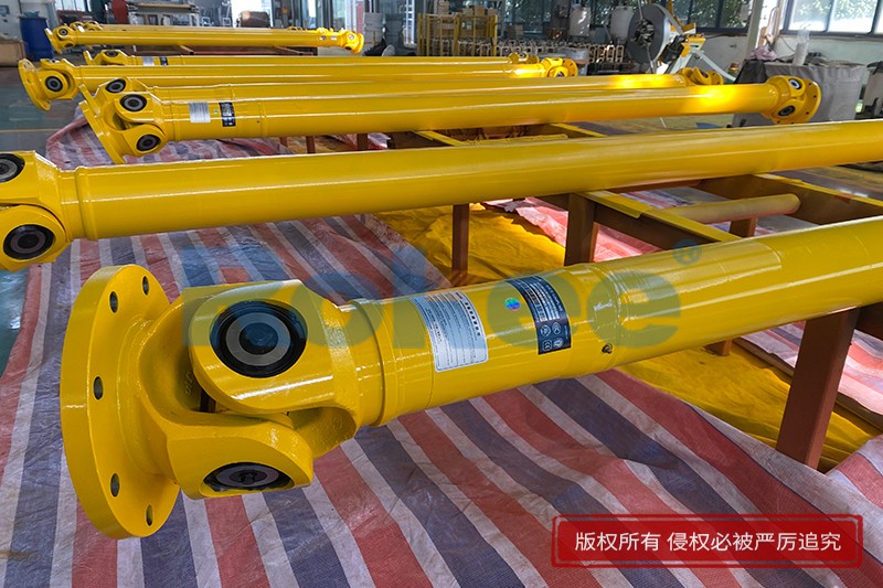
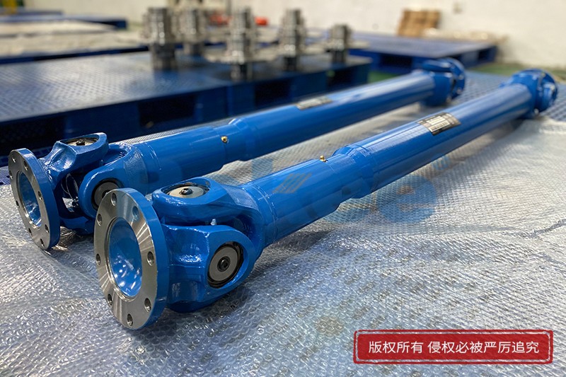
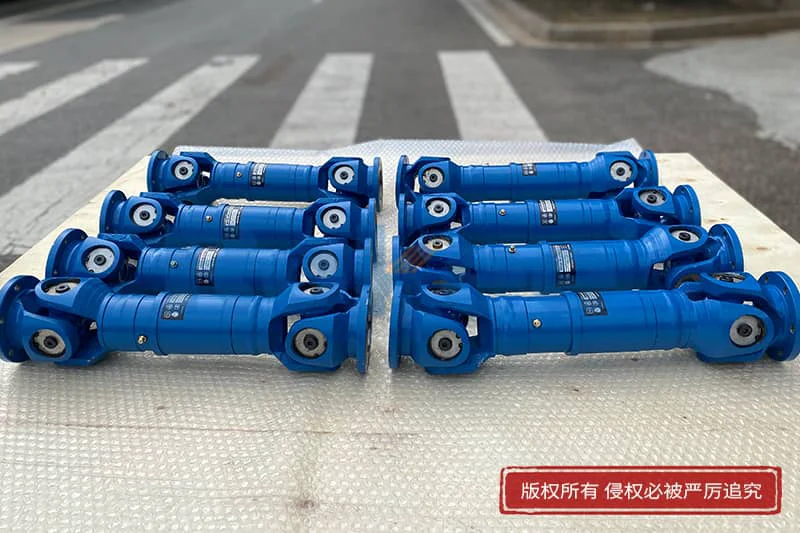
The 3D digital model of cardan couplings has extensive application scenarios in multiple industrial fields. In the mechanical manufacturing industry, the model can be used to guide the processing and production of physical prototypes. Manufacturers can extract processing dimensions, assembly tolerance and structural process parameters from the 3D model to complete the blank making, cutting and finishing of coupling parts, and effectively control the processing accuracy. In the field of mechanical equipment maintenance, the standardized 3D model serves as a disassembly and assembly guide. Maintenance personnel can view the internal assembly sequence and hidden connection structure of the coupling through the model, which improves the efficiency of equipment overhaul and fault replacement. In mechanical teaching and scientific research, the visualized 3D model simplifies the abstract transmission principle, enables learners to clearly understand the motion logic and force transmission path of the coupling, and provides a convenient experimental carrier for mechanical principle research and structural innovation exploration. In addition, in the design of special mechanical equipment such as engineering machinery and transportation equipment, the 3D model can be embedded into the overall mechanical system for matching simulation, so as to verify the compatibility between the coupling and other transmission components and ensure the rationality of the overall mechanical structure design.
With the continuous innovation of digital technology, the 3D modeling technology of cardan couplings is also developing towards high precision, intelligence and multi-functional integration. Traditional static 3D models can only realize structural display and simple motion simulation, while the emerging intelligent digital models integrate sensor parameter embedding and real-time data feedback functions. By adding physical attribute parameters such as material wear coefficient and friction resistance coefficient to the model, the dynamic operation state of the coupling under complex working conditions such as high speed, heavy load and variable temperature can be simulated more accurately. At the same time, combined with virtual reality technology, the immersive interaction of the coupling 3D model is realized. Researchers can rotate, disassemble and assemble the model in the virtual scene, and intuitively observe the internal wear and structural deformation of the coupling during operation. In the future, with the popularization of additive manufacturing technology, the optimized 3D model can be directly connected with 3D printing equipment to realize rapid prototyping production of couplings, shorten the product research and development cycle, and reduce the trial-production cost of structural improvement schemes.
In conclusion, the 3D model of cardan couplings is an important technical achievement combining mechanical structure principle and digital modeling technology. It not only accurately reproduces the basic structure and motion characteristics of cardan couplings, but also provides a reliable digital research platform for motion simulation, mechanical analysis, structural optimization and engineering application. The model makes up for the deficiencies of traditional two-dimensional drawings in spatial expression and dynamic analysis, simplifies the research difficulty of complex transmission mechanisms, and promotes the standardized and refined development of coupling design and manufacturing technology. In the context of the rapid development of modern mechanical engineering, further optimizing the modeling accuracy of cardan coupling 3D models, expanding simulation functions and enriching application scenarios will help to continuously improve the comprehensive performance of cardan couplings, provide stronger technical support for the stable operation of various mechanical transmission systems, and lay a solid foundation for the innovation and upgrading of universal coupling mechanical technology.
- Tags:
- Cardan Couplings ,
- sandwich panel line ,
- sandwich panel machine
- pu sandwich panel machine
« 3D Model of Cardan Couplings » Latest Update Date: May 21, 2026
https://www.rokeecoupling.net/blog/3d-model-of-cardan-couplings.html