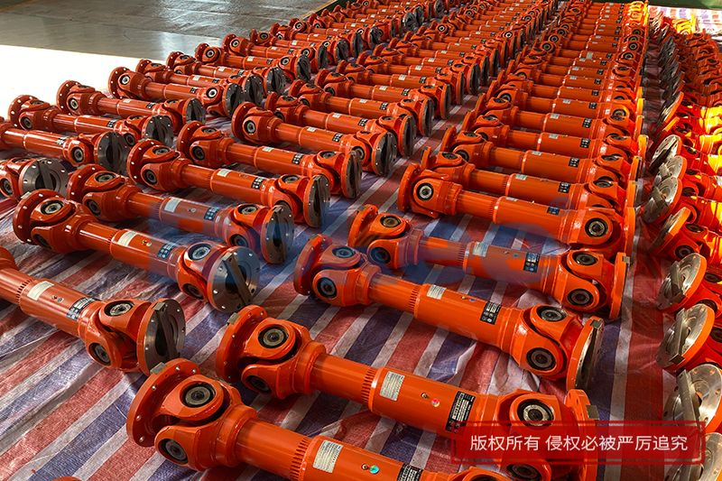
As a core mechanical transmission component widely adopted in mobile machinery, industrial transmission systems and general power transmission equipment, cardan drive shafts solve the technical bottleneck of torque and rotational motion transmission between non-collinear intersecting shafts. Conventional two-dimensional engineering drawings can only reflect planar contour dimensions and assembly relations of cardan drive shafts, which fail to intuitively present spatial motion trajectories, internal component matching states and hidden structural stress distribution characteristics during actual operation. With the continuous upgrading of digital mechanical design technology, three-dimensional modeling has become an indispensable technical means for the whole life cycle research of cardan drive shafts, covering structural design verification, kinematic performance simulation, mechanical strength prediction, assembly error detection and pre-production process optimization. The construction and multi-scene application of high-precision 3D models effectively make up for the defects of traditional planar design methods, reduce repeated modification links in physical prototype trial production, and improve the overall design rationality and operational reliability of cardan drive shaft assemblies under complex working conditions.

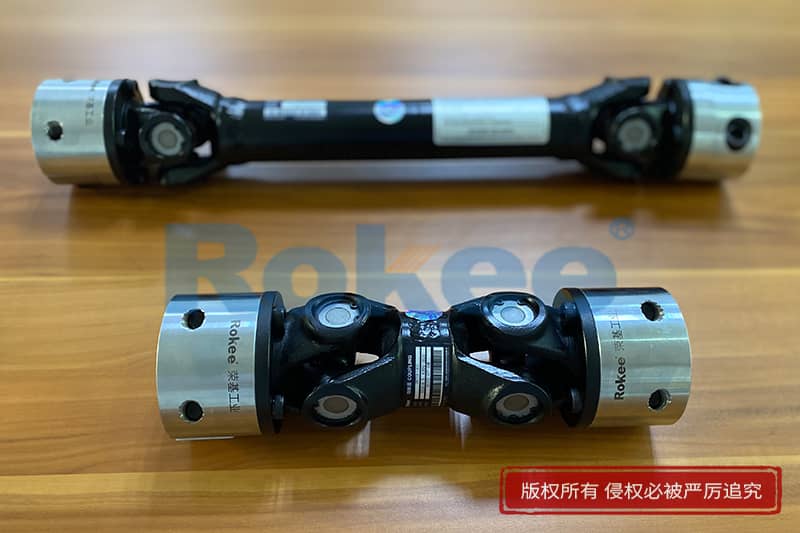
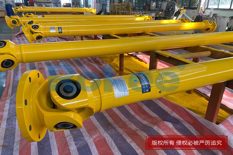
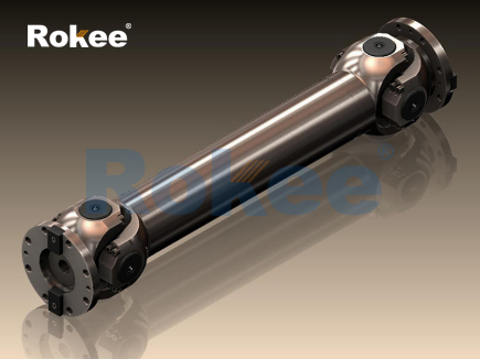
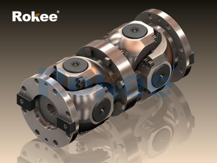
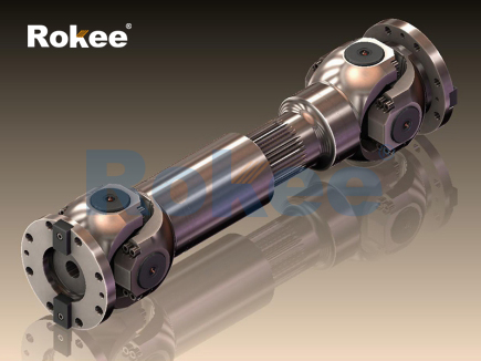
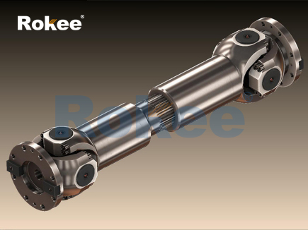
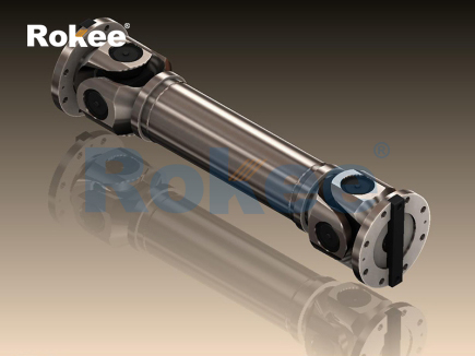
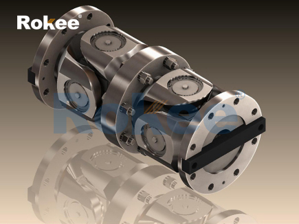
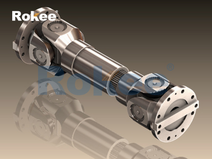
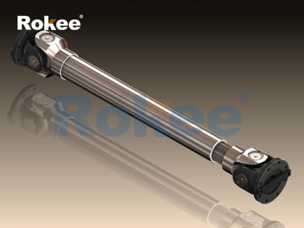
To build a complete and functionally accurate 3D model of a cardan drive shaft, designers must first fully clarify the overall structural composition and matching logic of each sub-component, which lays a solid geometric foundation for subsequent parametric modeling and assembly simulation. A standard dual universal joint cardan drive shaft assembly mainly consists of front and rear joint yokes, cross spider components, needle roller bearing sets, intermediate transmission shaft tube, telescopic spline pair and connecting flanges. Each component bears independent mechanical functions and interacts closely during power transmission. The cross spider is the core force-bearing and motion switching part of the universal joint, with four mutually perpendicular journal structures distributed evenly in space, which are embedded into the inner cavity of joint yokes through needle roller bearings to realize flexible angular deflection between connected shafts. The intermediate shaft tube is divided into solid shaft and hollow tubular shaft according to load requirements; hollow tubular structures are more commonly used in medium and high-speed transmission scenarios because they reduce overall structural inertia while maintaining sufficient torsional stiffness and raising critical rotational speed. The telescopic spline pair installed in the middle section compensates for axial distance changes between driving ends and driven ends caused by mechanical vibration, equipment position deviation and dynamic displacement during operation, avoiding additional axial extrusion stress inside the overall transmission assembly. Different from fixed rigid transmission shafts, cardan drive shafts allow angular deflection ranging from 5 degrees to 45 degrees between input and output shafts, and the matching clearance between bearings and cross journals directly determines transmission efficiency, operation noise and service life of the whole shaft system, all of which need to be accurately restored in 3D model construction.
The whole process of establishing a high-precision 3D model of cardan drive shafts is divided into three progressive stages: independent part modeling, virtual assembly of components and overall model calibration based on actual working conditions. In the independent part modeling stage, designers adopt sketch-based feature modeling and surface scanning modeling methods according to different structural characteristics of parts. For regular axisymmetric parts such as shaft tubes, flanges and spline shafts, two-dimensional contour sketches are first drawn on the reference plane, and then rotary stretching and chamfering feature commands are used to complete rapid modeling, with precise control over dimensional parameters including shaft diameter, wall thickness, flange bolt hole distribution and spline tooth profile angle. For complex spatial curved surface parts represented by cross spiders and joint yokes, simple rotary modeling cannot meet accuracy requirements, so spatial scanning and mixed cutting feature operations are adopted to restore irregular transition fillets, bearing mounting holes and positioning grooves. Special attention is paid to the modeling of needle roller bearing assemblies: dense needle rollers, bearing outer rings and sealing gaskets are modeled separately according to actual dimensional matching tolerances, instead of simplified integrated solid structures, because tiny clearance changes between needle rollers and journals will produce obvious differences in friction characteristics and dynamic load distribution in subsequent kinematic simulation.
After finishing all independent part models, virtual assembly is carried out following the actual mechanical assembly sequence of cardan drive shafts to realize constraint matching between parts. During assembly, basic fixed constraints are applied to the intermediate shaft tube and joint yokes at both ends, and rotating clearance constraints with reasonable tolerance values are set between cross spiders and needle roller bearings, as well as between bearing outer rings and yoke mounting holes to simulate real flexible rotating pairs in physical equipment. Meanwhile, displacement matching constraints are added to the internal and external spline structures of the telescopic mechanism to reserve effective axial sliding stroke consistent with actual working requirements. In this process, the 3D modeling platform can automatically detect interference problems between components in real time. Common interference phenomena include excessive overlap between cross spider journals and bearing inner walls, unreasonable axial position of spline pairs leading to limited telescopic stroke, and spatial collision between flange structures and peripheral mounting parts. Unlike manual interference inspection relying on two-dimensional drawings, 3D virtual assembly can capture microscopic interference errors below 0.1 millimeter, which effectively eliminates assembly hidden dangers that are difficult to find in traditional design stages and avoids scrappage of physical parts caused by assembly mismatches in later processing.
After completing geometric modeling and interference-free assembly of the whole shaft system, the calibrated 3D model can be imported into multi-functional simulation modules to conduct kinematic characteristic analysis, which is the core value of digital modeling beyond visual structure display. The inherent kinematic characteristic of a single cardan universal joint is periodic uneven angular velocity transmission: when there is a fixed deflection angle between the input shaft and output shaft, the instantaneous rotational speed of the driven shaft will fluctuate periodically within one rotation cycle, bringing torsional vibration and additional alternating load to the whole transmission system. Relying on the established 3D assembly model, designers can set operating parameters including input rotating speed, fixed shaft deflection angle and cyclic working time to observe real-time motion state of each joint component. The simulation results can intuitively display the rotation angle change curve of the driven shaft, the periodic swing amplitude of cross spiders and the contact friction track between needle rollers and journals under different deflection angles. Moreover, by comparing kinematic data of single universal joint transmission and dual universal joint symmetric transmission, the compensation mechanism of dual cardan shafts can be verified visually: the phase difference of two sets of universal joints eliminates the uneven angular velocity fluctuation of a single joint, realizing approximate constant-speed torque transmission between input and output ends. This intuitive kinematic simulation based on 3D models helps designers optimize installation phase angles of front and rear universal joints in the early design stage, reduce torsional vibration amplitude of the shaft system, and improve transmission stability under long-term continuous operation.
In addition to kinematic motion analysis, the 3D model of cardan drive shafts also supports finite element structural stress simulation, which realizes quantitative prediction of stress concentration, deformation and fatigue failure risks of key components under complex dynamic loads. Before finite element analysis, mesh division is carried out for the overall 3D assembly model, adopting refined mesh division for key force-bearing areas such as cross spider journals, spline tooth surfaces and shaft tube middle sections, and relatively sparse mesh for low-load non-key structures to balance simulation accuracy and computing efficiency. Then actual working boundary conditions are set according to real application scenarios: fixed support constraints are applied to one end flange, continuous torque load matching actual transmission demand is applied to the other end, and combined loads including bending stress caused by shaft deflection and axial friction stress caused by spline telescopic movement are superimposed. Static stress simulation results show that obvious stress concentration areas are mainly distributed at the journal root of cross spiders and the tooth root position of telescopic splines, which are consistent with the actual failure positions of physical cardan shafts in engineering applications. Transient dynamic simulation further reflects periodic stress changes inside components with shaft rotation, revealing that alternating stress generated by cyclic rotation is the main inducement of fatigue cracks and wear failure of universal joint parts. With the visualized stress cloud diagram generated by the 3D simulation model, designers can targeted optimize local structures, such as increasing transition fillet radius at journal roots and optimizing spline tooth profile curves, to reduce local stress peaks and enhance overall structural durability of the drive shaft.
Compared with traditional design and test methods relying on physical prototypes, the application of 3D models of cardan drive shafts brings comprehensive improvements in design cycle, test cost and optimization efficiency for mechanical transmission research. In the past, verifying the structural rationality and motion performance of a new type of cardan drive shaft required processing multiple sets of physical prototypes, conducting bench vibration tests, durability wear tests and assembly performance tests one by one. The whole test cycle lasts several weeks, and any structural defect requires repeated modification and reprocessing of prototypes. By virtue of digital 3D models, all structural verification, motion simulation and strength analysis can be completed in virtual digital environments in the early design stage, and design schemes can be adjusted rapidly according to simulation feedback without consuming any physical processing materials. Meanwhile, the parameterized modeling function of the 3D platform enables batch iterative optimization of drive shaft structures: designers only need to modify core dimensional parameters such as shaft tube length, universal joint deflection range and spline stroke, and the overall assembly model and corresponding simulation data will be updated automatically, which greatly accelerates the iterative optimization progress of drive shaft design schemes. In addition, standardized 3D models can realize seamless data docking with numerical control processing equipment, realizing direct conversion from digital model data to production processing paths, reducing drawing interpretation errors in traditional manual processing links and improving overall machining accuracy of cardan drive shaft parts.
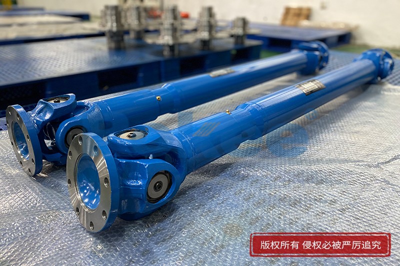
In practical engineering application scenarios, 3D models of cardan drive shafts also play an important role in equipment installation guidance, daily maintenance training and fault diagnosis assistance. For large mechanical transmission equipment equipped with long-distance cardan drive shaft groups, on-site construction personnel can view the dynamic assembly animation derived from 3D models to master standardized installation sequences, accurate bolt fastening sequences and reserved deflection angle ranges during equipment assembly, avoiding installation errors caused by misunderstanding two-dimensional drawings. For mechanical maintenance training, the exploded view animation of the 3D model can clearly show the internal nested relation of hidden parts inside universal joints, which solves the problem that internal structures are invisible after physical assembly and improves the intuitiveness of disassembly and maintenance training. When the drive shaft system has operation faults such as abnormal vibration, increased noise and transmission jamming, maintenance personnel can compare actual fault phenomena with motion simulation data of the 3D model, quickly locate fault causes including excessive bearing clearance, insufficient spline lubrication and mismatched universal joint installation phase, and formulate targeted maintenance plans efficiently.
Despite the mature application of current conventional geometric 3D modeling and basic simulation technologies for cardan drive shafts, there are still optimization directions worthy of in-depth exploration combined with emerging digital design technologies. Most existing 3D models adopt linear material parameter settings, which cannot fully fit the nonlinear mechanical characteristics of metal materials under high-speed impact, long-term fatigue load and variable temperature working environments. Subsequent model optimization can introduce nonlinear material constitutive models to restore real-time material performance changes of drive shaft parts under extreme working conditions, improving the accuracy of simulation results. Besides, most current simulation researches separate kinematic analysis and structural stress analysis, failing to realize bidirectional coupling calculation between real-time motion state and dynamic stress distribution. Building coupled motion-stress collaborative simulation 3D models can more truly reflect the working state of cardan drive shafts under actual complex composite loads. In addition, combining 3D drive shaft models with digital twin technology can realize real-time mapping between virtual digital models and physical operating drive shaft equipment, monitor operating state data such as rotating speed, vibration amplitude and stress value of physical shafts in real time, and realize early warning of potential fatigue failure and vibration resonance risks during long-term operation.
In conclusion, 3D modeling technology has completely reconstructed the whole research and development logic of cardan drive shafts, covering full-link digital support from initial structural design, intermediate performance simulation and optimization to later production, installation and maintenance. The high-precision geometric model restores real structural characteristics and assembly relations of each component, kinematic simulation reveals inherent motion laws and vibration defects of universal joint transmission mechanisms, and finite element stress analysis realizes quantitative evaluation of structural strength and fatigue risks. As mechanical transmission equipment develops towards high rotating speed, heavy load and long service life, cardan drive shafts will face more complex and diverse working conditions, and higher requirements will be put forward for design accuracy and operational stability. Continuous upgrading and iterative optimization of 3D digital models will further promote the performance improvement of cardan drive shaft products, provide more reliable digital technical support for the design and operation of modern mechanical transmission systems, and expand the application boundary of cardan transmission mechanisms in high-end mechanical equipment.
- Tags:
- Cardan Drive Shafts ,
- sandwich panel line ,
- sandwich panel machine
- pu sandwich panel machine
« 3D Model of Cardan Drive Shafts » Latest Update Date: Jun 12, 2026
https://www.rokeecoupling.net/blog/3d-model-of-cardan-drive-shafts.html