Barrel couplings stand as one of the most versatile mechanical connection components widely applied in industrial transmission systems, serving to link two rotating shafts and transmit torque while accommodating minor mechanical displacements generated during equipment operation. The alignment of barrel couplings constitutes a core procedure in mechanical installation and commissioning, which directly determines the operational stability, service life and mechanical efficiency of the entire transmission system. Improper alignment is one of the primary triggers for mechanical failures of rotating equipment, often leading to abnormal vibration, excessive component wear, shaft deformation and even unexpected shutdown of mechanical systems. In industrial production scenarios involving continuous operation, subtle misalignment errors of barrel couplings can gradually amplify mechanical stress during long-term rotation, resulting in irreversible damage to shafts, bearings and coupling structures. Therefore, an in-depth understanding of alignment principles, standard operating procedures, error control methods and maintenance strategies for barrel couplings is essential to ensure the reliable and durable operation of mechanical transmission equipment.

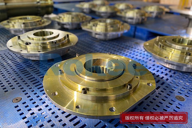
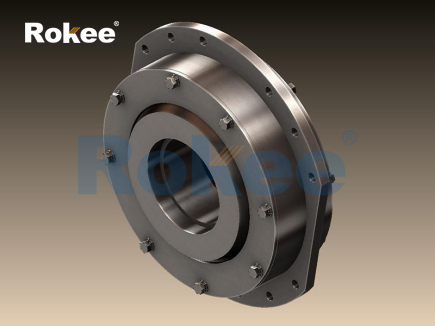
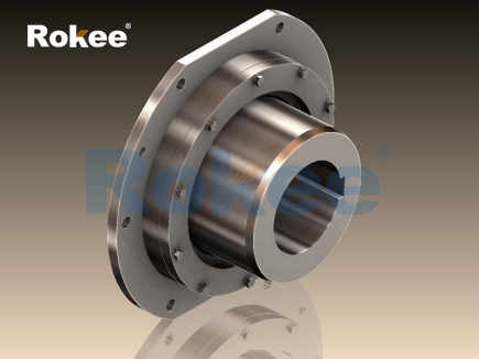
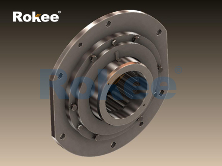
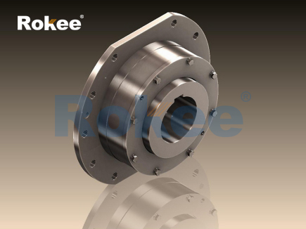
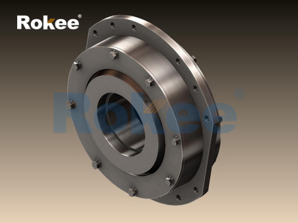
To fully comprehend the importance of barrel coupling alignment, it is necessary to clarify the basic structural characteristics and mechanical working logic of barrel couplings. Different from rigid coupling structures that strictly limit shaft displacement, barrel couplings adopt a special cylindrical matching structure with internal flexible coordination space. This structural design enables the coupling to bear moderate radial, axial and angular displacements in the working state, so as to buffer the mechanical vibration generated by equipment operation and offset the tiny position deviations between driving shafts and driven shafts. Despite the inherent displacement tolerance of barrel couplings, such tolerance has clear physical limits. Any misalignment exceeding the allowable range will break the stress balance of the coupling structure. During high-speed rotation, misaligned barrel couplings will produce periodic alternating stress on the contact surfaces of internal components, which intensifies friction and abrasion between matching parts. Moreover, unbalanced mechanical force will be transmitted along the shaft system to bearings and other auxiliary components, accelerating the aging and damage of vulnerable parts. In long-term industrial application data, most premature failures of barrel couplings are not caused by material fatigue or structural defects, but by unregulated alignment during the installation stage.
In actual industrial installation scenarios, the misalignment forms of barrel couplings are mainly divided into three basic types, and most alignment failures are the composite superposition of these three deviation forms. The first type is radial misalignment, also known as parallel offset deviation. This deviation manifests as the parallel dislocation of the central lines of two connected shafts, where the axial lines remain parallel without angular inclination, but there is a certain radial spacing between the central axes. Radial misalignment usually occurs due to uneven base support of equipment or position deviation in the initial installation stage. The second type is angular misalignment, which means that the central lines of the two shafts intersect at a certain angle instead of being kept in a straight line. This deviation is mostly caused by the inclination of the equipment mounting base or the uneven stress of the shaft body. When the shaft rotates, the angular deviation will produce continuous torsional shear force on the barrel coupling, leading to asymmetric wear of the inner wall of the coupling barrel. The third type is axial misalignment, referring to the excessive gap or extrusion between the end faces of the two half-couplings along the axial direction. Barrel couplings cannot bear continuous axial load, so excessive axial displacement will change the matching clearance of internal structures, resulting in poor lubrication and local stress concentration. In practical engineering cases, single-type misalignment is relatively rare, and most working conditions are accompanied by two or three composite deviations, which increases the difficulty of alignment construction and puts forward higher requirements for measurement accuracy.
The alignment process of barrel couplings follows a standardized logical sequence, covering pre-installation preparation, surface inspection, data measurement, deviation calculation, position adjustment and post-adjustment verification. Each link is closely connected, and any careless operation in a single step will affect the overall alignment effect. In the pre-installation preparation stage, it is necessary to clean all connecting parts of the coupling thoroughly to remove surface dust, metal debris, rust spots and residual lubricants. Impurities attached to the matching surface will cause tiny protrusions and depressions, which interfere with the accuracy of measurement data and leave hidden dangers for stable operation. Meanwhile, the stability of the equipment base should be checked to ensure that there is no looseness or deformation of the base support structure. The vibration generated by the unstable base will directly interfere with the alignment calibration work. In addition, all fastening bolts need to be preliminarily debugged to maintain a flexible fastening state, which facilitates the fine adjustment of the shaft position in the subsequent correction process. It is also essential to determine the reference shaft during the preparation stage; in general, the relatively fixed shaft with stable load and simple stress is selected as the benchmark, and the position of the other movable shaft is adjusted to complete the alignment matching, which can effectively reduce the repeated adjustment workload and improve calibration efficiency.
Measurement is the core link of barrel coupling alignment, and the accuracy of measurement data determines the rationality of the subsequent adjustment scheme. According to different industrial precision requirements, measurement methods can be divided into conventional simple measurement and high-precision professional measurement. Simple measurement tools include straight rulers and feeler gauges, which are suitable for low-speed transmission equipment with low alignment precision requirements. Operators use a straight ruler to fit the outer circular surface of the two half-couplings to observe the radial gap deviation, and use a feeler gauge to detect the parallelism of the end faces by measuring the axial gap at multiple positions. This measurement method is easy to operate with low implementation cost, but it is greatly affected by human visual judgment, resulting in limited measurement accuracy and obvious human error. For medium and high-speed mechanical equipment with strict precision standards, dial indicators and laser alignment instruments are adopted for high-precision measurement. During the measurement, the detection instruments are fixed on the coupling shell, and the two shafts are rotated synchronously at a constant speed. Data records are collected at intervals of ninety degrees in the circumferential direction to obtain the radial runout and axial runout values of the coupling. Multiple groups of measured data can eliminate the detection error caused by the slight deformation of the coupling itself and the surface processing tolerance, so as to obtain the real misalignment amount of the shaft system.
After completing the data collection, the measured deviation values need to be converted into specific adjustment quantities through professional calculation logic. The core calculation principle is to convert radial offset and angular inclination into the gasket thickness difference at the equipment base and the horizontal displacement distance of the fixed support. In the calculation process, the axial distance between the equipment support points, the outer diameter of the coupling and the length of the shaft body must be fully considered to avoid miscalculation caused by ignoring the deflection characteristics of the shaft system. For large-scale transmission equipment with long intermediate shafts, the natural deflection of the shaft body under gravity will cause slight axis deviation, which needs to be compensated in the alignment calculation. After confirming the accurate adjustment parameters, the fine position correction of the movable shaft is carried out. The vertical height deviation is usually adjusted by adding or removing gaskets at the equipment base, while the horizontal offset is calibrated by fine-tuning the fixing bolts of the support. In the adjustment process, repeated correction is required instead of one-time positioning; each slight adjustment should be accompanied by secondary measurement to track the change of deviation values until all errors are controlled within the allowable range. It is worth noting that soft tools such as copper rods should be used for auxiliary tapping during position adjustment to avoid surface damage and structural deformation of couplings and shafts caused by hard impact.
Many external interference factors need to be avoided in the alignment operation of barrel couplings to prevent deviation rebound after calibration. Thermal deformation is one of the most common interference factors. During the continuous operation of mechanical equipment, the friction of internal moving parts will generate heat, which causes thermal expansion of shafts, couplings and equipment shells. The thermal expansion degree of different metal structures varies, leading to subtle changes in the relative position of the two shafts. Therefore, for equipment with large temperature rise during operation, cold-state alignment and thermal compensation calculation must be carried out. The reserved deviation margin in the cold state can offset the position displacement caused by thermal expansion in the working state, so as to ensure the optimal alignment state in the high-temperature operation stage. In addition, the uneven stress of the pipeline connection will also affect the alignment stability. Excessive tensile or compressive force of the connecting pipeline will pull the equipment shell, resulting in slow deviation of the shaft axis. Hence, all connected pipelines should be kept in a naturally relaxed state before alignment to eliminate additional external stress.
After completing the alignment adjustment, a standardized post-inspection procedure is required to verify the alignment quality of barrel couplings. Firstly, all fastening bolts should be tightened symmetrically in a staggered sequence to avoid local stress concentration caused by one-sided excessive fastening. The tightening torque should be kept uniform to ensure the consistent compression degree of each connecting part. Secondly, the synchronous rotation test of the shaft system should be carried out. The rotating resistance of the coupling is manually detected; if the rotation is smooth without obvious jamming and stagnation, it indicates that the internal matching gap is reasonable. On the contrary, abnormal rotation resistance means there is excessive local extrusion or residual misalignment. Finally, no-load trial operation is conducted. The equipment runs at a low speed for a certain period, and the vibration amplitude, noise frequency and temperature change of the coupling area are monitored. Stable vibration, low noise and gentle temperature rise are the intuitive judgment criteria for qualified alignment. If there is sharp vibration and abnormal metal friction noise, the equipment should be shut down immediately for secondary inspection and correction.
Scientific maintenance after alignment is an important guarantee to maintain the long-term alignment accuracy of barrel couplings. In the daily operation cycle, regular visual inspection should be conducted to observe whether there is oil leakage, surface abrasion and bolt looseness on the coupling surface. The lubrication state of the internal matching structure cannot be ignored; reasonable lubrication can reduce friction resistance and buffer mechanical impact, and the deterioration of lubricating oil should be regularly checked and replaced. For mechanical equipment running in harsh working environments such as high dust and high humidity, dust-proof and anti-corrosion protection measures need to be strengthened to prevent corrosive substances from damaging the coupling matching surface and causing gap changes. With the extension of service time, the aging deformation of the equipment base and the fatigue settlement of the support structure will lead to slow drift of the shaft position. Therefore, regular alignment re-inspection is required in the maintenance cycle, and minor deviations found in the inspection process should be corrected in a timely manner to avoid the gradual amplification of small errors into large-scale mechanical failures.
The economic and mechanical value of high-precision alignment of barrel couplings is reflected in multiple dimensions. From the perspective of component loss control, standardized alignment can reduce the friction loss between coupling components, lower the wear rate of bearings and sealing parts, and effectively extend the overall service life of the transmission system. From the perspective of energy consumption optimization, misaligned couplings will generate additional mechanical resistance during rotation, increasing the power consumption of driving equipment. Accurate alignment minimizes unnecessary power loss and improves the transmission efficiency of mechanical energy. From the perspective of production stability, good alignment state reduces equipment vibration and noise, optimizes the working environment of mechanical equipment, and lowers the failure rate of unplanned shutdowns caused by coupling faults. In the long-term industrial operation cycle, the manpower and material resource costs saved by standardized alignment far exceed the time and energy invested in the calibration process.
In conclusion, the alignment of barrel couplings is a systematic and rigorous mechanical engineering work, which integrates theoretical calculation, precise measurement and standardized operation. It covers the whole life cycle of equipment installation, commissioning, operation and maintenance. The three typical misalignment forms in actual operation have different adverse effects on the coupling structure, and the interference factors such as thermal deformation and external stress need to be avoided in the alignment process. Through scientific pre-preparation, accurate data measurement, reasonable deviation correction and perfect post-inspection maintenance, the alignment accuracy of barrel couplings can be effectively guaranteed. With the continuous upgrading of industrial mechanical equipment, the rotation speed and load-bearing capacity of transmission systems are constantly improving, which puts forward higher precision requirements for coupling alignment. Mastering professional alignment technologies and standard operation specifications is not only the basic requirement of mechanical installation work, but also the key to ensure efficient, stable and long-term operation of industrial transmission equipment. Reasonable alignment management can maximize the structural performance of barrel couplings, reduce mechanical operation risks, and create stable economic benefits for industrial production activities.
- Tags:
- Barrel Couplings ,
- sandwich panel line ,
- sandwich panel machine
- pu sandwich panel machine
« Alignment of Barrel Coupling » Latest Update Date: May 21, 2026
https://www.rokeecoupling.net/blog/alignment-of-barrel-coupling.html