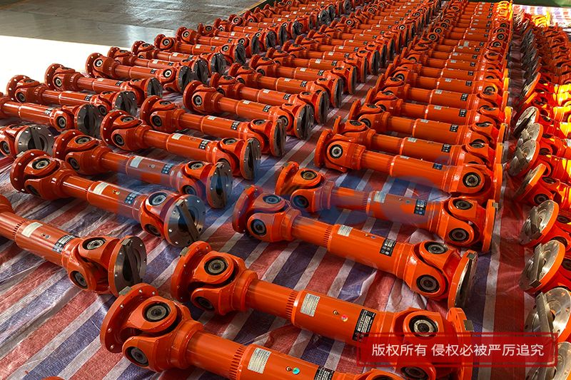
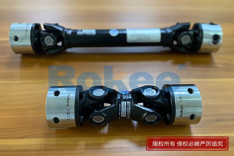
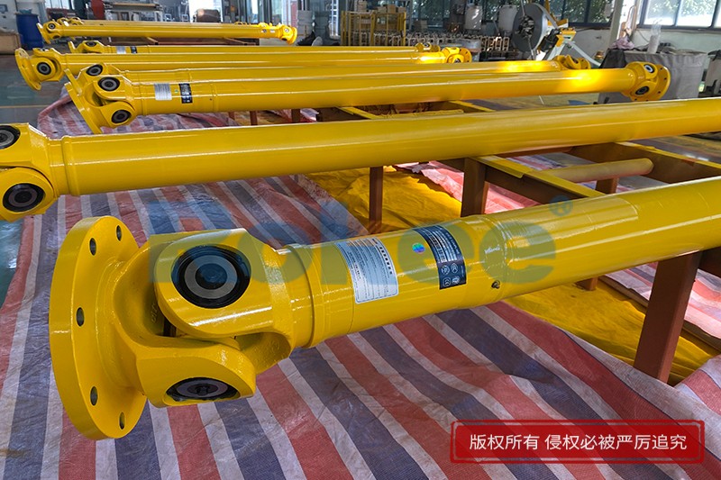
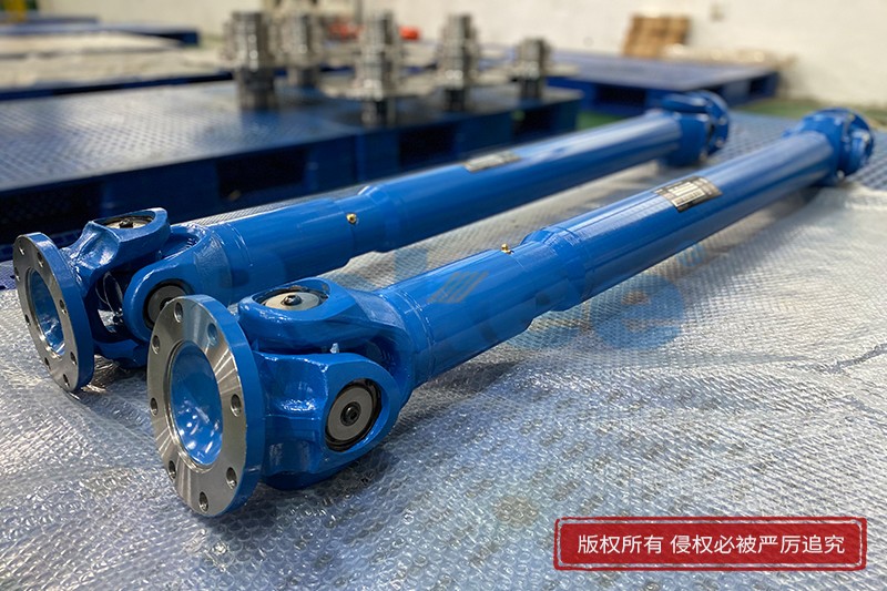
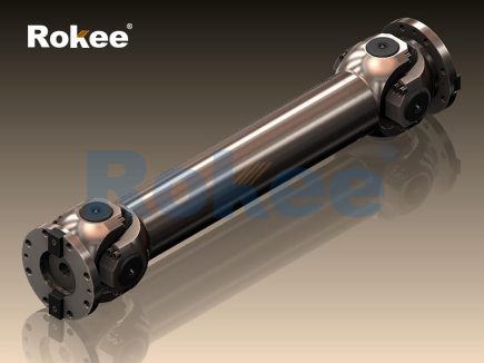
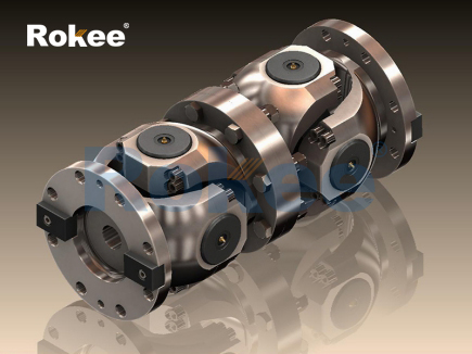
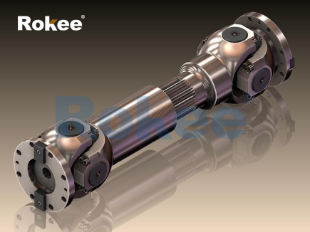
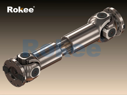
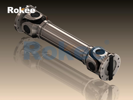
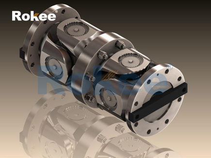
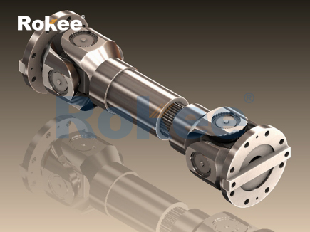
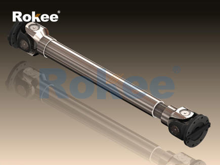
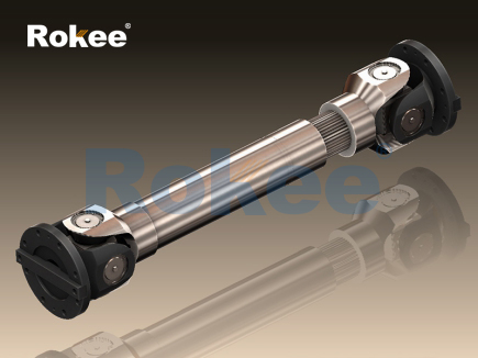
The universal joint coupling, also commonly known as a Cardan joint, serves as a mechanical connection component designed to transmit rotary motion between two shafts whose axes are not aligned along a single straight line. At its core, the basic working principle relies on a cross-shaped intermediate component, often called a spider, which links two yoke assemblies mounted on the ends of the driving and driven shafts. Each arm of the cross piece connects to a bearing set inside the yoke, allowing limited rotational swing between the yokes. When the driving shaft spins, it turns the first yoke, and torque transfers through the cross member to the second yoke and the driven shaft. This structure permits angular misalignment between the connected shafts, which distinguishes it from rigid couplings that demand precise coaxial positioning. A critical feature of a single universal joint is its non-constant velocity characteristic. If the two shafts maintain an angular offset, the rotational speed of the driven shaft fluctuates twice per full rotation of the driving shaft. Even when the input shaft rotates at a steady speed, the output shaft accelerates and decelerates cyclically. This speed variation creates vibration and dynamic load, which becomes more obvious as the shaft angle increases. Engineers must understand this inherent motion behavior to avoid unexpected mechanical stress and premature component wear in practical machinery applications. Careful consideration of the operating angle is essential, as excessive angular deflection amplifies speed oscillation and reduces the service life of the bearings and cross elements within the joint assembly.
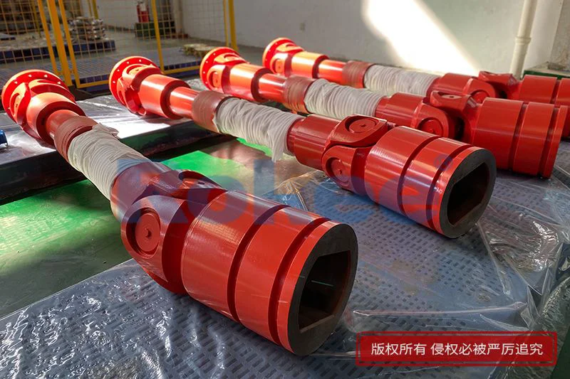
To mitigate the fluctuating velocity issue of a single universal joint, most practical transmission systems adopt paired universal joint couplings arranged in sequence. The dual joint setup uses two universal joints connected by an intermediate shaft, and the installation orientation must follow a specific rule to balance motion. The yokes attached to the intermediate shaft need to be aligned on the same plane, and the angular misalignment between the driving shaft and the intermediate shaft should match the angle between the intermediate shaft and the driven shaft. When these geometric conditions are met, the speed fluctuation produced by the first joint gets counteracted by the second joint. The acceleration and deceleration cycle of the first joint’s output cancels out the speed variation introduced by the second joint, and the final driven shaft regains a nearly constant rotational velocity matching the input shaft. This arrangement expands the usable angular offset range while smoothing torque delivery. Even with paired joints, there are practical limits to the misalignment angle. Larger angles raise friction inside the bearing assemblies and increase the bending forces acting on the intermediate shaft. System designers also need to control the length of the intermediate segment, because an overly long intermediate shaft may introduce bending vibration under high rotational speeds, which can undermine the stability of the whole transmission system.
The internal force transfer process inside a universal joint coupling involves complex interactions between contact surfaces and rolling bearing elements. As torque passes through the coupling, compressive force acts on the cross spider’s four arms, and these forces transfer to the needle bearings fitted between the cross arms and the yoke bores. The needle bearings reduce sliding friction and allow the yokes to pivot freely relative to the cross piece during rotation. During operation, the contact points between the bearing rollers and the cross arm constantly shift as the yoke swings back and forth within the allowed angular range. This repeated cyclic contact creates alternating mechanical loads on the bearing surfaces. If the applied torque exceeds the designed load capacity, permanent deformation can form on the cross arms or bearing races, which impairs the pivoting movement and causes binding. Lubrication plays a vital role in sustaining reliable operation. Proper lubricant fills the gaps between needle rollers and contact surfaces, lowers friction heat, and prevents metal-to-metal wear. Without regular lubrication, heat buildup will degrade bearing surfaces rapidly, leading to noise, increased backlash, and eventual failure of the joint. The selection of lubricant type and maintenance interval depends heavily on operating temperature, rotational speed, and the magnitude of transmitted torque.
Universal joint couplings can accommodate multiple types of shaft misalignment simultaneously, setting them apart from many other coupling forms. Besides angular misalignment, the assembly tolerances and thermal expansion in machinery often create small amounts of axial and radial displacement between the connected shafts. The pivoting capability of the joint allows it to absorb these minor displacements without imposing large extra loads onto the connected equipment. Axial displacement arises when shafts expand or contract due to temperature changes, or from small positional shifts during equipment startup and shutdown. Radial offset happens when the centerlines of the two shafts sit parallel but separated by a small distance. It is worth noting that the coupling can only handle limited amounts of combined misalignment. If radial offset becomes too large, the required swing angle of the joint increases sharply, raising dynamic forces and wear rates. In such cases, additional sliding components may be integrated into the assembly to accommodate greater axial movement. Designers evaluate all forms of expected misalignment at the design stage to select a suitable joint configuration and prevent overload during normal and transient operating conditions.
Dynamic performance under variable operating conditions is another key aspect of universal joint coupling operation. When machinery starts up or encounters sudden load changes, shock torque transmits through the coupling. The joint structure can absorb a certain level of shock because the bearing contacts allow small elastic deformation, but heavy repeated shock loads will fatigue the cross and bearing components over time. Rotational speed also influences the working state significantly. At low speeds, the main concern is static torque transfer and bearing friction. At high rotational speeds, centrifugal force acts on the moving parts inside the joint. Unbalanced mass in the yoke or cross assembly generates centrifugal force that creates vibration and bending stress. Dynamic balancing is therefore required for couplings used in high-speed transmission systems. Vibration produced by unbalanced components can spread to the connected equipment, affecting precision and generating noise. Resonance is another risk. If the rotational frequency matches the natural vibration frequency of the shaft assembly, amplified vibration can damage bearings and supporting structures. Engineers conduct dynamic analysis to avoid resonant operating ranges and ensure stable operation across the full working speed range.
Wear mechanisms and failure modes directly reflect how universal joint couplings degrade during long-term use. The most common wear location is the needle bearing assembly. Rolling contact fatigue occurs when repeated cyclic load creates tiny surface cracks on the bearing rollers and cross arm journals. These cracks gradually expand and eventually lead to surface flaking. Abrasive wear takes place if solid contaminants enter the bearing cavity, scratching the polished contact surfaces. Seal structures around the bearings are designed to block dust and moisture. Once seals degrade, contamination accelerates wear and may cause corrosion on the cross and bearing surfaces. Backlash grows as wear accumulates, which means a small rotation of the input shaft no longer immediately moves the output shaft. Excessive backlash is problematic for systems requiring precise motion control. Other failure modes include twisting fracture of the cross spider under extreme torque and bending fatigue of the yoke arms. Regular inspection monitors backlash, noise level, seal integrity and lubricant condition. Early detection of wear allows maintenance actions before catastrophic failure interrupts machine operation.
Universal joint couplings find wide application across many mechanical systems because of their unique ability to transmit torque through angled shafts. Power transmission systems in mobile machinery often rely on these couplings to transfer rotation between components that shift position during operation. In such equipment, relative movement between driving and driven components continuously changes the shaft angle, and the universal joint adapts to this dynamic misalignment. Stationary industrial machinery also uses these couplings where layout constraints prevent perfectly coaxial shaft arrangement. The compact structural form makes installation convenient in spaces with limited room for transmission components. Compared with other flexible coupling options, universal joint couplings can support much larger angular misalignment while transmitting high torque. However, they are not ideal for every scenario. Systems needing ultra-smooth rotation at very high speeds may favor alternative coupling designs to reduce vibration. Applications with frequent reversing motion also need careful assessment of shock load effects on bearings. The suitability of a universal joint coupling always depends on a comprehensive match between its mechanical characteristics and the requirements of the target transmission system.
Advancements in material selection and manufacturing continue to improve the performance and durability of universal joint couplings. Traditional alloy steels remain the primary material for cross spiders and yokes, offering high strength and resistance to fatigue under cyclic torque. Advanced heat treatment processes modify the surface hardness of contact areas to resist rolling wear while keeping the core material tough enough to withstand shock loads. Precision machining ensures close dimensional tolerances for bearing seats and cross arm surfaces, minimizing clearance and reducing vibration. Modified seal designs extend service life by improving resistance to extreme temperatures and harsh environmental conditions such as dust, water spray and chemical exposure. Some optimized structural variants reduce the mass of rotating elements to lower centrifugal force and vibration at high speeds. While the fundamental working principle of the universal joint has stayed unchanged, these refinements expand its usable operating range and reduce maintenance demands. Even with improved materials, the basic limitation of single-joint non-constant velocity remains. Designers still must apply the dual joint layout whenever uniform output rotation is required. Continuous refinement ensures universal joint couplings remain a reliable and practical torque transmission solution for mechanical systems that need to operate with angular shaft misalignment.
- Tags:
- Universal Joint Couplings ,
- sandwich panel line ,
- sandwich panel machine
- pu sandwich panel machine
« Working Principle of Universal Joint Couplings » Latest Update Date: Oct 20, 2026
https://www.rokeecoupling.net/blog/working-principle-of-universal-joint-couplings.html