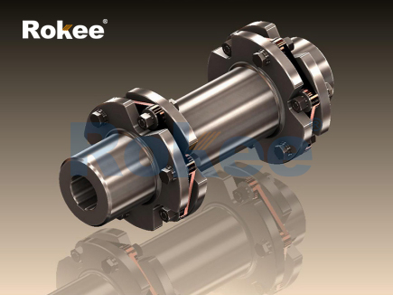
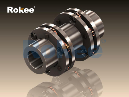
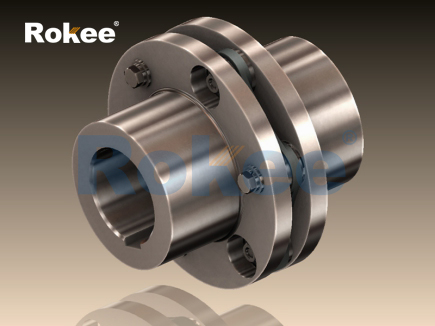
The 3D modeling of flexible diaphragm coupling serves as a core technical carrier for visualizing structural composition, analyzing mechanical performance, and optimizing industrial transmission system design. As a high-performance metal flexible transmission component widely applied in precision mechanical transmission scenarios, flexible diaphragm couplings rely on the elastic deformation of thin metal diaphragm components to complete torque transmission and shaft misalignment compensation. The establishment of a refined 3D model enables engineers to break through the limitations of two-dimensional plane drawings, accurately restore the spatial assembly relationship, microscopic deformation characteristics and dynamic operation state of each component, and provide reliable digital support for structural optimization, performance verification and practical engineering application. Different from rigid transmission couplings and other flexible coupling types, the structural design of flexible diaphragm couplings features high integration and deformation controllability, and the 3D digital model can fully present the unique mechanical logic and structural advantages of this component in a visualized and quantifiable manner.

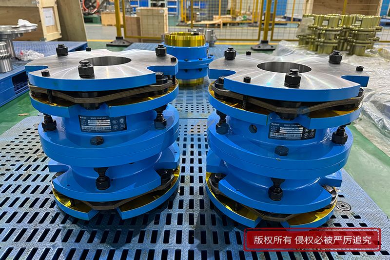
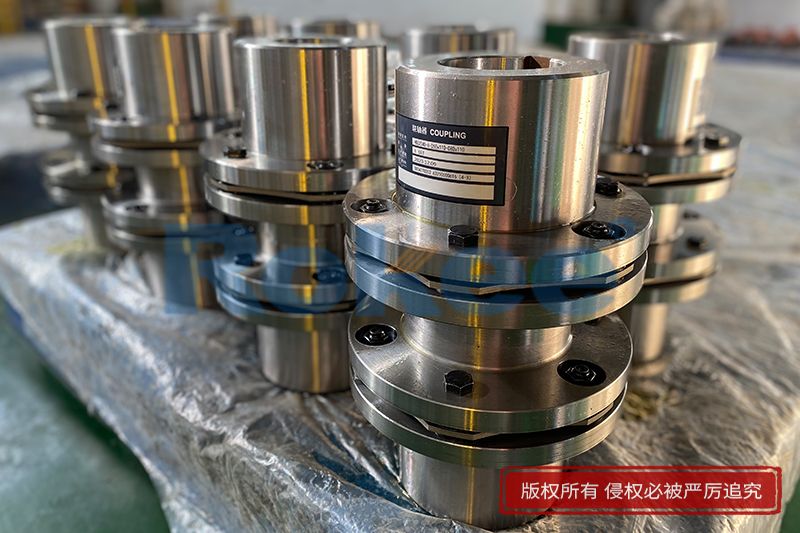
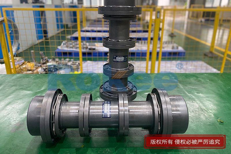
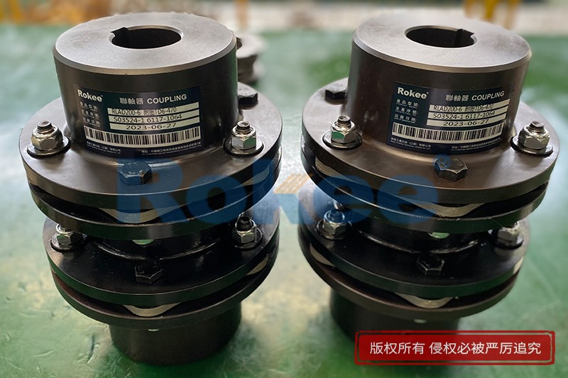
The overall structural construction of the flexible diaphragm coupling 3D model follows the actual mechanical assembly logic and completely reproduces the core component composition of the coupling, including symmetrically arranged coupling flanges, elastic diaphragm groups, connecting fasteners and intermediate transition structures. Each component in the model is designed with precise dimensional parameters and spatial position relationships, which are consistent with the mechanical design criteria of industrial transmission components. The flange parts on both sides are designed with high-rigidity integral structures, which are used for stable connection with the driving shaft and driven shaft respectively. In the 3D model, the flatness and coaxiality of the flange mounting surface are accurately calibrated, simulating the rigid fixing state of the coupling during actual equipment assembly, ensuring that the torque input and output ends maintain stable basic support during high-speed operation.
The elastic diaphragm group is the core functional component of the flexible diaphragm coupling and the key modeling object of the 3D digital model. The model accurately restores the thin-plate spatial structure of the metal diaphragm, including the geometric characteristics of uniform thickness, regular outline and symmetric force-bearing holes. Different from traditional rigid component modeling, the 3D model of the diaphragm group adds flexible deformation attribute settings based on solid structural modeling, which can truly reflect the elastic torsion, bending and stretching deformation of the diaphragm under torque load and shaft displacement conditions. Multiple groups of diaphragm laminated structures are arranged in an orderly manner in the model, and the gap coordination and force transmission path between single diaphragms are accurately simulated, realizing the integration of structural morphology and mechanical attribute modeling. This refined modeling method effectively solves the problem that traditional 2D drawings cannot display the three-dimensional deformation trend and multi-directional force-bearing state of the diaphragm.
Connecting fasteners, as the key force-transmitting and positioning components of the coupling, are also modeled in full detail in the 3D digital system. The model standardizes the spatial distribution, locking state and assembly gap of fastener groups, and simulates the uniform torque transmission effect of fasteners between flanges and diaphragm groups. In the actual transmission process, fasteners not only undertake the fixed assembly function, but also bear cyclic shear force and tensile force during equipment operation. The 3D model can visually show the force concentration area of fasteners under different working conditions, and lay a foundation for subsequent structural strength optimization and fatigue resistance analysis. Meanwhile, the model reserves reasonable assembly tolerance parameters consistent with industrial application standards, ensuring that the digital model is highly consistent with the physical prototype in assembly accuracy and operation compatibility.
The core value of the flexible diaphragm coupling 3D model is reflected in the simulation and verification of its working mechanism. In industrial mechanical transmission systems, it is difficult to achieve absolute coaxial alignment between the driving shaft and the driven shaft due to processing errors, assembly deviations, equipment operation vibration and thermal deformation. Slight axial displacement, angular deflection and radial offset between shafts will cause additional load and vibration wear in the transmission process, which seriously affects the stability and service life of mechanical equipment. The established 3D model can simulate various misalignment states between shafts in actual working conditions, and intuitively present the elastic deformation process of the diaphragm group under different displacement deviations.
When axial displacement occurs between the two shafts, the 3D model shows that the metal diaphragm produces reversible stretching and contracting deformation along the axial direction, which absorbs the axial spacing change of the transmission shafting and maintains continuous and stable torque transmission. In the case of angular misalignment, the diaphragms on both sides produce synchronous bending and torsion deformation, balancing the angle deviation between the driving end and the driven end, and avoiding rigid collision and torque loss caused by shaft deflection. For radial offset, the laminated diaphragm group realizes flexible adaptation through micro torsion deformation of different areas, ensuring the synchronous rotation of the two shafts without generating additional bending moment. The visualized deformation process presented by the 3D model enables technical personnel to clearly grasp the misalignment compensation principle of flexible diaphragm couplings and accurately evaluate the deformation range and force-bearing limit of the component under extreme working conditions.
In terms of material attribute modeling, the 3D model of flexible diaphragm coupling adopts accurate mechanical parameter settings matching with high-strength elastic metal materials. The diaphragm part is endowed with excellent elastic modulus, tensile strength and fatigue resistance parameters, which conform to the material performance characteristics of industrial high-precision transmission components. The flange and fastener parts are set with high rigidity and high hardness material attributes to ensure that no plastic deformation or structural failure occurs under long-term high-load operation. The differential material attribute design in the model truly restores the mechanical coordination relationship between the flexible functional part and the rigid connecting part of the coupling, ensuring that the simulation results of torque transmission efficiency, deformation compensation ability and structural fatigue life are close to the actual operation data of physical equipment.
Dynamic simulation analysis based on the 3D model further verifies the excellent operating performance of flexible diaphragm couplings. In the high-speed rotation simulation state built by the model, the coupling maintains zero-backlash torque transmission, and the diaphragm group only produces micro elastic deformation in the allowable range, without rigid impact and transmission clearance. Compared with elastic sleeve couplings and gear couplings, the flexible diaphragm coupling displayed by the 3D model has more stable high-speed operation performance, lower vibration and noise, and no lubrication maintenance requirements in the working process. The model can simulate the long-term cyclic operation state of the coupling under variable torque and variable speed conditions, analyze the stress distribution law and fatigue wear trend of key parts, and provide data support for improving the structural durability and operational stability of the coupling.
The structural optimization design based on 3D modeling has greatly improved the comprehensive performance of flexible diaphragm couplings. By adjusting the geometric parameters such as diaphragm thickness, outline shape and hole distribution in the 3D model, technicians can optimize the balance between the flexibility and torsional stiffness of the coupling. The integral diaphragm structure designed and verified by the model has higher torsional rigidity and torque transmission capacity, while the special-shaped diaphragm layout can provide larger deformation compensation range and adapt to more complex shafting misalignment working conditions. The parametric design function of the 3D model realizes the rapid iteration of multiple structural schemes, avoids the time cost and material waste of repeated physical prototype production, and significantly improves the efficiency and accuracy of coupling performance optimization.
In industrial engineering application scenarios, the refined 3D model of flexible diaphragm coupling provides important technical support for equipment assembly, fault prediction and system matching. In the equipment assembly stage, the 3D visualization model can guide standardized assembly operations, avoid assembly errors caused by unclear spatial structure, and ensure the coaxiality and assembly accuracy of coupling installation. In the equipment operation stage, the dynamic simulation data of the 3D model can predict the deformation state and stress change of the coupling under different working loads, judge the operation health state of the component, and realize early warning of fatigue failure and structural damage. Meanwhile, the 3D model can realize matching analysis with different types of transmission equipment, verify the adaptability of the coupling in high-temperature, high-speed and corrosive working environments, and expand the application scope of flexible diaphragm couplings in precision machine tools, power transmission equipment, automated production lines and high-speed rotating machinery.
The digital characteristics of the 3D model also lay a foundation for the standardized design and intelligent manufacturing of flexible diaphragm couplings. The unified three-dimensional digital parameter system realizes the standardization of coupling structural design, dimensional matching and performance evaluation, and solves the problems of inconsistent design standards and poor component universality in traditional manual design. On the basis of the 3D model, finite element analysis can be further carried out to quantitatively calculate the stress concentration, deformation displacement and safety factor of each component, accurately define the optimal working range and load limit of the coupling, and provide reliable theoretical basis for industrial selection and engineering application. With the continuous improvement of modeling accuracy and simulation technology, the 3D digital model of flexible diaphragm coupling will develop towards higher precision, stronger dynamic simulation ability and more intelligent performance prediction, and provide more comprehensive technical support for the upgrading and optimization of modern mechanical transmission systems.
- Tags:
- Flexible Diaphragm Couplings ,
- sandwich panel line ,
- sandwich panel machine
- pu sandwich panel machine
« 3D Model of Flexible Diaphragm Couplings » Latest Update Date: Jul 10, 2026
https://www.rokeecoupling.net/blog/3d-model-of-flexible-diaphragm-couplings.html