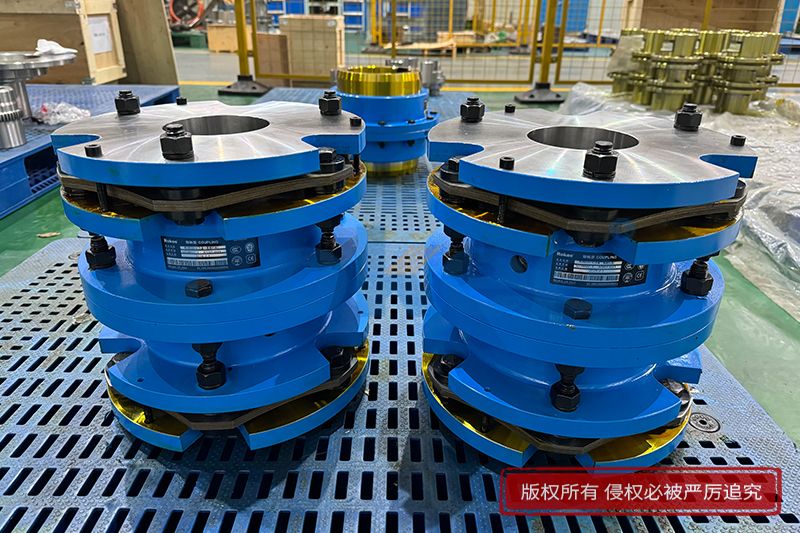
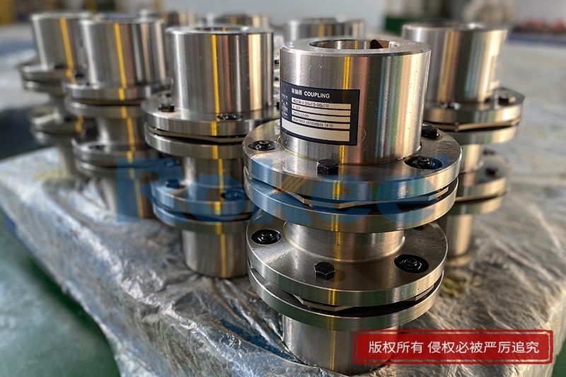
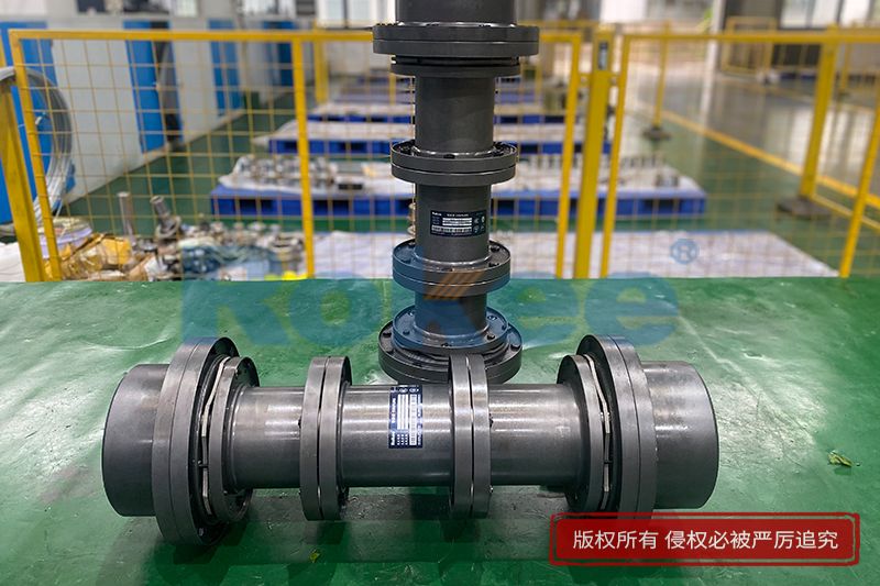
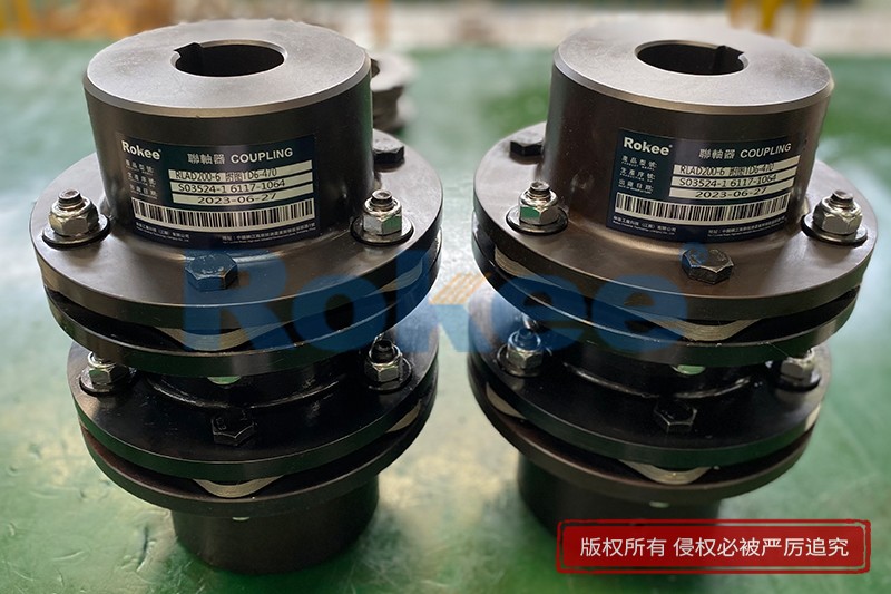
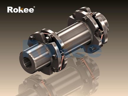
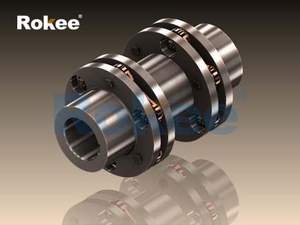
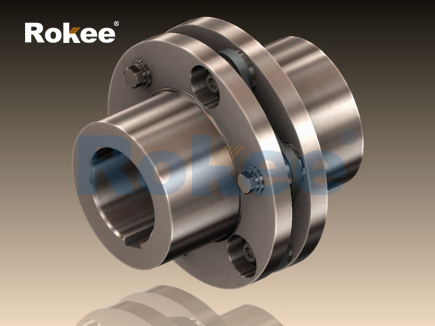
The membrane coupling serves as a flexible connecting component used to transmit torque between two rotating shafts while accommodating minor misalignments that inevitably emerge during equipment operation. Its core working principle relies on the elastic deformation of thin metal membrane stacks, which are clamped alternately by bolt sets to the hub flanges on both driving and driven sides. When power starts to transfer, rotational torque pulls the membrane material, generating tensile force across the surface of each individual membrane sheet rather than shear stress. Unlike elastomeric couplings that depend on rubber compression, metal membranes maintain their structural integrity through controlled elastic stretching. Small amounts of axial, angular and parallel offset between shafts can be absorbed by slight bending and stretching of the stacked membranes. Each membrane layer distributes load evenly to prevent localized stress concentration, and the laminated structure shares deformation across multiple thin sheets instead of relying on a single thick plate. During steady rotation, the membrane assembly rotates synchronously with both shafts without relative sliding, eliminating friction and wear that commonly occur in gear or jaw coupling designs. This sliding-free operation removes the need for lubrication, simplifying long-term maintenance routines. Even with continuous cyclic rotation, the membrane material returns to its original shape after load removal within the elastic limit, allowing repeated deformation without permanent damage. The basic transmission mechanism remains consistent across different structural layouts, where torque flows through bolts into the membrane pack and then onward to the opposite shaft hub, creating a continuous rotary power path.

As torque transmits through the membrane coupling, different types of shaft misalignment trigger distinct forms of elastic deformation within the membrane stacks. Angular misalignment appears when the centerlines of the driving and driven shafts intersect at an angle, causing one side of the membrane pack to stretch while the opposite side compresses during each full rotation. Parallel misalignment occurs when shaft centerlines remain parallel but offset horizontally, forcing alternating bending of membrane layers as the coupling spins. Axial misalignment arises from thermal expansion of connected equipment, pushing or pulling the two hubs further apart or closer together and producing pure tensile or compressive strain on the membranes. All these deformations stay within the elastic range of the membrane material under normal operating conditions. The stacked arrangement helps limit peak stress on any single membrane sheet, spreading deformation over dozens of thin foils. It is important to note that the coupling can only accept limited misalignment values. Excessive offset will push the membrane past its elastic threshold, introducing permanent deformation and accelerating fatigue failure. Operators must align equipment carefully during installation to reduce baseline misalignment, so the membrane only bears small cyclic loads during routine running. The membrane’s ability to flex under these three forms of misalignment forms the foundation of its flexible performance, separating it from rigid couplings that cannot tolerate any shaft offset and will transfer all misalignment forces directly to bearing systems.
Material characteristics of the membrane directly define the coupling’s load capacity, fatigue resistance and service life under cyclic rotation. The membranes are usually made of thin metallic sheets with high tensile strength and excellent fatigue performance, selected to endure millions of repeated stretch and bend cycles. The material must maintain stable mechanical properties across a wide temperature range, resisting softening or brittle fracture when exposed to heat generated by connected machinery. Each sheet is precision processed to ensure uniform thickness and flatness, avoiding uneven stress distribution caused by surface defects or dimensional inconsistencies. Surface finish also matters greatly, as tiny scratches or machining marks can act as crack initiation points under cyclic loading. The stacked design uses multiple thin membranes instead of one thick plate because thinner sheets produce lower bending stress under the same deflection. Individual membranes are closely stacked but still allow slight relative sliding between layers under deflection, which further reduces peak stress. However, interlayer friction is minimal and does not create measurable wear in normal service. The material must also resist oxidation and corrosion in working environments, since rust spots can propagate into cracks under cyclic torque fluctuations. Any degradation of membrane material will gradually reduce the safe operating window for misalignment and torque, so regular visual inspection is necessary to identify surface corrosion or cracking before component failure happens.
Bolted clamping arrangement plays a critical role in transferring torque securely between flanges and membrane packs, and poor clamping directly undermines coupling function. Bolt holes are arranged in a circular pattern along the outer and inner edges of the membrane stack. Inner fasteners connect part of the membrane pack to one hub flange, while outer fasteners secure the remaining portion of the same membrane stack to the opposite hub flange. This alternating clamping pattern creates the cantilever-like segment of membrane between inner and outer bolt circles, which is the flexible section that deforms to absorb misalignment. Torque passes from the driving hub through inner bolts into the membrane material, crosses the flexible membrane segment, and then transfers outward through outer bolts to the driven hub. The preload applied to each bolt must be consistent, so every bolt carries an equal share of torque load. Uneven bolt tension concentrates force onto a small number of fasteners and corresponding membrane areas, leading to premature bolt loosening or membrane tearing. The contact surfaces between flanges and membrane edges must remain clean and flat to prevent point loads that cut into thin membrane sheets. Fasteners themselves experience cyclic tension during rotation, so they are designed to resist fatigue. The clamping system must hold the membrane stack firmly without slippage at the contact interfaces; once slipping occurs, friction marks form on membranes and fasteners, and torque transmission becomes unstable, accompanied by vibration and noise.
Vibration damping and dynamic response represent another key aspect of the membrane coupling’s working behavior. While the metal membrane itself has low inherent damping compared to rubber couplings, its rigid torque transmission characteristic preserves rotational stiffness under steady load. This high torsional stiffness means the angular deflection of the coupling under applied torque remains very small, maintaining precise rotational phase between driving and driven shafts. This property makes the coupling suitable for systems requiring accurate speed synchronization. However, low damping also means it does not absorb torsional vibration effectively. Torsional oscillations generated by reciprocating loads or speed fluctuations will pass through the coupling with little attenuation, and resonant conditions need to be avoided through system dynamic analysis. When misalignment exists, cyclic bending of the membranes produces periodic small forces that appear as vibration at twice the rotating frequency. If this vibration frequency matches the natural frequency of the whole shaft train, resonance develops and amplifies stress on membranes and connected bearings. The membrane coupling therefore changes the overall dynamic characteristics of the rotating system. Engineers evaluate torsional natural frequencies during system design to ensure operating speed stays away from critical resonance zones. Proper alignment reduces the excitation force from membrane bending, lowering vibration amplitude and lessening the cyclic fatigue load acting on the membrane stacks over time.
Failure modes reveal the physical limits of membrane coupling operation and reflect how its working principle breaks down when operating boundaries are exceeded. The most common failure mechanism is metal fatigue caused by repeated cyclic deformation of membranes. Each rotation cycle creates one full stretch-bend cycle in the membrane material. If misalignment stays above recommended limits, the amplitude of cyclic strain rises rapidly, and microcracks start to form at high-stress locations such as bolt hole edges. These cracks grow slowly under continued rotation until they cut through the membrane pack, interrupting torque transmission. Another failure type comes from excessive torque overload. A sudden torque spike stretches the membrane beyond its elastic limit, causing permanent yielding and tearing of the metal sheets. Corrosion can also accelerate failure; chemical attack creates surface pits that concentrate local stress and become crack origins even under normal torque and alignment conditions. Bolt loosening or fastener fatigue failure is less frequent but equally disruptive, as loss of clamping force stops reliable torque transfer. In many cases, early warning signs include rising vibration levels or audible noise before complete rupture. Understanding these failure paths highlights that the membrane coupling works reliably only when misalignment, torque load, temperature and environmental corrosion all stay within acceptable operating boundaries defined by the component’s mechanical design.
Installation and operation influence the actual working state of a membrane coupling, even though its fundamental principle stays unchanged once assembled. Before assembly, shaft positions need adjustment to minimize initial angular and parallel offset. Any residual misalignment becomes the baseline deflection that the membrane must accommodate continuously during rotation. When mounting, membrane stacks must not receive unintended twisting or bending during bolt tightening. Operators tighten bolts following a cross sequence to distribute clamping force evenly across the bolt circle. After startup, thermal expansion of connected equipment will alter shaft positions and introduce additional axial or angular misalignment, which the membrane absorbs through elastic deformation. During continuous running, the coupling rotates at the same speed as the connected shafts, and the membrane flexes cyclically with every revolution. Sudden load changes create transient torque peaks that briefly increase tensile stress across membrane sheets. Temperature changes affect material modulus and thermal expansion of hubs and membranes, slightly modifying stress distribution. Routine operation does not require lubrication, eliminating contamination risks and reducing routine service tasks. Operators monitor vibration and temperature trends to track coupling condition. If equipment foundation shifts over time, shaft misalignment increases gradually, raising cyclic stress on membranes. Regular checkups catch rising misalignment early and prevent fatigue damage from accumulating to a catastrophic failure event.
Membrane couplings find broad application across rotating machinery systems, and their working principle delivers unique advantages for many power transmission scenarios. In high-speed rotating equipment, low mass and balanced membrane packs produce minimal centrifugal load and can maintain stable rotation at elevated speeds. Their zero-backlash characteristic ensures immediate torque response without rotational play, which suits machinery demanding precise motion control. Since power transfer occurs through elastic deformation of metal membranes rather than flexible polymer materials, the coupling tolerates elevated operating temperatures where elastomeric couplings would degrade rapidly. It also resists degradation from many oils and chemical vapors present in industrial working environments. Compared with gear couplings, membrane types remove sliding contact surfaces, eliminating wear particles and the requirement for regular grease replenishment. The torsional stiffness remains stable throughout long service time, without aging or softening as seen in rubber flexible elements. However, the coupling has inherent limits: it cannot absorb large shock loads effectively, and its allowable misalignment capacity is smaller than many elastomeric alternatives. For these reasons, designers select membrane couplings when high torsional stiffness, speed capability and low maintenance are prioritized, while ensuring shaft alignment stays controlled and shock loads are limited. The simple but effective principle of torque transfer through laminated elastic metal membranes continues to make this coupling type a dependable solution for connecting rotating shafts in diverse mechanical power transmission arrangements.
- Tags:
- Disc Membrane Couplings ,
- Laminated Membrane Couplings ,
- Membrane Couplings ,
- Flexible Membrane Couplings ,
- Metal Membrane Couplings ,
- sandwich panel line ,
- sandwich panel machine
- pu sandwich panel machine
« Working Principle of Membrane Couplings » Latest Update Date: Oct 20, 2026
https://www.rokeecoupling.net/blog/working-principle-of-membrane-couplings.html