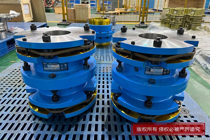
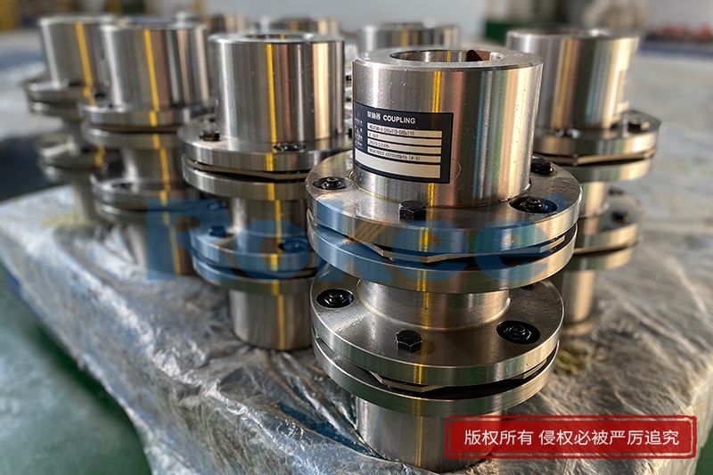
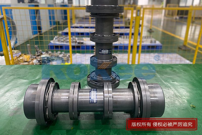
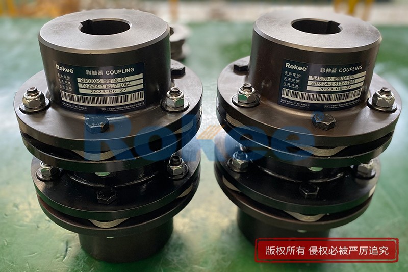
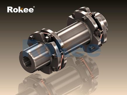
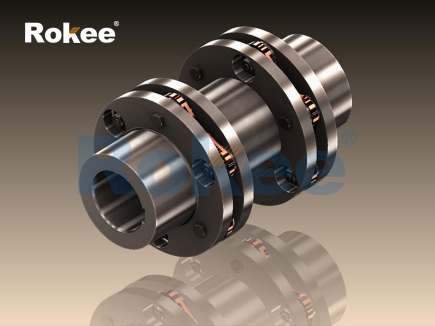
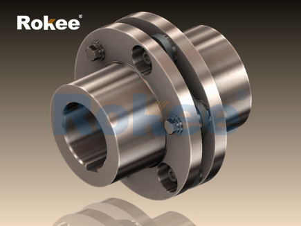
The plate coupling serves as a flexible mechanical connection designed to transmit torque between two rotating shafts while accommodating minor misalignments that inevitably arise during equipment assembly and operation. At the core of its working principle lies a stack of thin, metallic plates arranged alternately between two hub flanges, which are fastened together using high-strength fasteners. As one shaft rotates, torque is transferred from the driving hub through the fasteners to the series of plates, and then onward to the driven hub and the connected shaft. Unlike rigid coupling types that force perfect shaft alignment, the layered plate structure relies on the elastic deformation of these thin metal sheets to absorb positional deviations. When shafts experience radial, angular, or axial misalignment, the plates bend and stretch within their elastic limits rather than transferring excessive stress directly to the connected machinery. This elastic behavior prevents the build-up of heavy reaction forces that would otherwise damage bearings, seals and other precision components on the rotating equipment. The plates themselves are engineered to withstand repeated cyclic loading during continuous rotation, maintaining consistent torque transmission without permanent deformation under normal operating conditions. All movement associated with misalignment is confined to the flexing of the plate pack, eliminating sliding or rolling contact between internal parts, which also reduces wear and avoids the need for lubrication over long service periods. This fundamental design trait makes the plate coupling distinct from many other flexible coupling options that depend on rubber or polymer elements, as the metal plates retain stable mechanical properties across a wide range of operating temperatures.
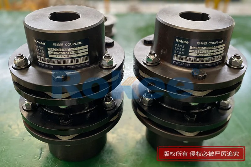
The transfer of torque within a plate coupling follows a predictable path that begins at the driving shaft hub and distributes load evenly across the entire plate assembly. Each fastener passes through corresponding holes on the plates, clamping the plate stack securely against the flange faces of both hubs. As rotational force is applied to the driving hub, tension develops in sections of the metal plates positioned between adjacent fastener sets. These tension forces carry torque around the circular arrangement of fasteners, passing load progressively through the plate pack to the fasteners mounted on the driven hub. The distribution of tension across multiple plates spreads mechanical stress, preventing any single plate from bearing the full torque load during operation. When the direction of rotation reverses, the regions of tension within the plate stack shift accordingly, and the plates flex in the opposite direction to accommodate the reversed torque flow. The geometry of the plate layout directly influences how stress spreads across the material; longer plate spans between fastener points allow greater flexibility for misalignment compensation, while shorter spans increase stiffness and torque capacity. It is important to recognize that the plates do not twist as a whole unit. Instead, localized bending and tensile strain occur in discrete segments between fasteners, keeping stress concentrations within safe limits. This load sharing mechanism ensures reliable power transmission even when vibration introduces small fluctuations in torque magnitude throughout the rotation cycle.
Angular misalignment compensation represents one of the key functional capabilities enabled by the elastic plate structure of the coupling. Angular misalignment occurs when the centerlines of the two connected shafts intersect at a slight angle rather than running perfectly parallel. In this state, the distance between corresponding fastener positions on the driving and driven hubs varies slightly around the full circle of rotation. As the coupling turns, the metal plates repeatedly flex to adjust for this changing gap between fasteners. Plates on one side of the coupling stretch slightly while plates on the opposite side relax during each rotation cycle, all remaining within their elastic range. This cyclic bending absorbs the angular offset and prevents bending moments from being fed back into the shaft bearings. The maximum allowable angular offset is determined by the thickness, material selection and overall diameter of the plate pack. Excessive angular misalignment forces repeated high strain on the plates, accelerating fatigue and shortening service life. When operating within designed limits, the plate flexure happens smoothly with minimal resistance and low hysteresis loss. Unlike couplings that rely on elastomers, metal plates do not experience creep under sustained angular deflection, so alignment performance remains stable over thousands of operating hours. The coupling can handle continuous rotation with consistent response to angular offset, and the elastic recovery of the plates returns them to their original shape once the misalignment load is removed.
Radial misalignment, another common form of shaft offset, is managed by the combined flexure of the entire plate stack. Radial misalignment takes place when the shaft centerlines run parallel but are displaced sideways from one another. In this condition, the plate assembly must bend laterally to bridge the offset between the two hubs. The stacked plates work together like a series of thin springs to accommodate this side-to-side displacement. Each plate contributes a small amount of lateral flexibility, and the cumulative effect of the whole pack allows the coupling to maintain torque transfer without imposing large side loads onto the connected shafts. Radial displacement creates a cyclic bending load on the plates for every full rotation of the equipment. Larger radial offsets amplify the magnitude of cyclic strain, raising the risk of metal fatigue over time. For this reason, practical installation aims to minimize radial offset while relying on the coupling’s flexibility to absorb residual misalignment that cannot be fully eliminated during assembly. The stiffness of the plate pack directly affects the reaction force generated by radial misalignment. Thinner plates produce lower stiffness and lower reaction loads, but they also reduce the maximum torque rating of the coupling. Designers balance these two factors to match the demands of the rotating system. Because there are no sliding surfaces, accommodating radial misalignment does not create friction or abrasive wear inside the coupling assembly.
Axial displacement compensation allows the plate coupling to absorb small changes in the distance between the two hubs along the shaft centerline. Axial movement can arise from thermal expansion of shafts and equipment casings during warm-up, or from minor end float of rolling element bearings. When the gap between hubs increases or decreases, the plate stack stretches or compresses along the axis. The thin metal plates bend axially to adjust the overall length of the coupling assembly. This axial flexibility prevents the generation of large thrust forces that could push or pull against bearings and internal machine components. The amount of allowable axial movement is limited by the plate geometry; excessive axial displacement creates high tensile or compressive stress that may permanently deform the plates. Axial motion occurs in combination with angular and radial misalignment in most real-world installations, so the plate pack must handle multiple forms of deflection simultaneously. When several types of misalignment exist at once, the combined strain on the plates must stay under the fatigue threshold of the plate material. The elastic nature of the metal plates means that once axial displacement returns to its nominal position, the plates revert to their original geometry. This capability removes the need for complex sliding components to handle thermal growth, simplifying the overall mechanical arrangement of the drive train.
Vibration damping and dynamic response characteristics of plate couplings stem from the material behavior of the metallic plate pack. While metal plate couplings are stiffer than flexible couplings that use rubber elements, they still offer enough elasticity to moderate peak torque shocks during start-up, shut-down and sudden load changes. When transient torque spikes occur, the plates deflect elastically to absorb part of the shock energy, reducing the impact transferred to the driven equipment. The low internal friction within the plate assembly means hysteresis losses remain small during normal cyclic operation. This property reduces heat generation inside the coupling, which is beneficial for high-speed applications where temperature rise can degrade mechanical performance. At the same time, the stiffness of the plate coupling influences the natural frequency of the complete rotating system. Engineers analyze the torsional stiffness of the plate pack to avoid operating speeds that coincide with torsional resonance, which would amplify vibration and induce destructive plate fatigue. Minor torsional vibration present during steady operation is mitigated by the distributed flexibility of the multiple plates. Because all flexibility comes from solid metal, dynamic performance does not degrade with aging, unlike polymer-based flexible elements that harden, soften or crack after long exposure to heat and chemical agents. This stable dynamic behavior supports consistent performance in equipment that runs continuously for extended periods.
Fatigue resistance stands as a critical consideration in the long-term operation of plate couplings, given the repeated cyclic strain experienced by the plates with every rotation. Each cycle of rotation creates bending and tensile stress fluctuations within the plate material, a form of cyclic loading that can eventually lead to fatigue cracking if stress levels remain too high. The thin plates are manufactured from materials with carefully controlled fatigue strength to withstand millions of load cycles. Stress concentrations are reduced through precision machining of plate holes and smooth edge finishing, as sharp notches or rough surfaces act as initiation points for fatigue cracks. Operating conditions such as high speed, combined misalignment and frequent torque reversals all accelerate fatigue accumulation. Visual inspection of the plate pack can reveal signs of fatigue, including fine surface cracks, plate buckling or permanent deformation. Once cracks develop, the structural integrity of the plate stack declines rapidly, and the coupling can no longer safely transmit torque. Proper installation to limit misalignment is the most effective way to extend plate service life, as it keeps cyclic strain low. Even under ideal alignment, gradual fatigue will occur over a very long operating time, so scheduled inspection intervals help identify degradation before component failure. The multi-plate design provides a degree of redundancy; minor damage to one plate may not immediately stop torque transmission, though prompt replacement remains necessary to prevent cascading failure.
The practical advantages and application boundaries of plate couplings follow directly from their working principle based on elastic plate flexure. The absence of lubrication requirements is a major benefit, as there are no contacting surfaces that require grease or oil to reduce friction and wear. This eliminates maintenance tasks related to lubricant replenishment, leakage control and contamination of surrounding equipment. The compact structure of the plate coupling allows installation in tight spaces where other flexible coupling types cannot fit. It maintains high torsional stiffness while retaining flexibility for misalignment, making it suitable for systems that require precise rotational synchronization between driving and driven shafts. However, the plate coupling is not suitable for situations involving very large misalignment values, because the limited elastic deflection range of metal plates cannot accommodate extreme offset without risking fatigue failure. Environments with heavy abrasive dust or corrosive media may degrade plate surfaces over time, requiring protective surface treatments for the metal components. The working principle also means that plate couplings are less effective at damping severe vibration compared to couplings with soft elastomer inserts. When selected and installed correctly, the plate coupling delivers dependable torque transmission across diverse rotating machinery. Its operation relies purely on controlled elastic deformation of thin metal plates, balancing flexibility for misalignment and structural strength for power transfer to protect connected equipment and sustain stable long-term operation.
- Tags:
- Plate Couplings ,
- sandwich panel line ,
- sandwich panel machine
- pu sandwich panel machine
« Working Principle of Plate Couplings » Latest Update Date: Oct 20, 2026
https://www.rokeecoupling.net/blog/working-principle-of-plate-couplings.html