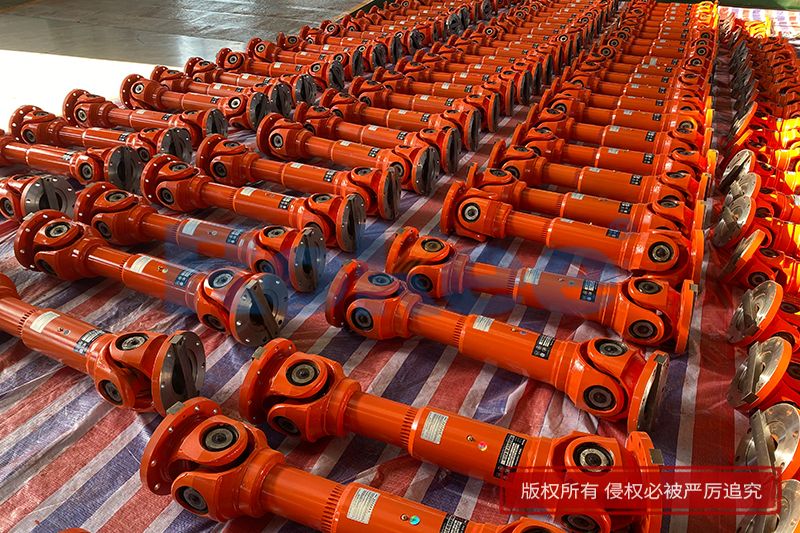
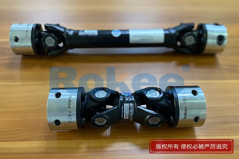
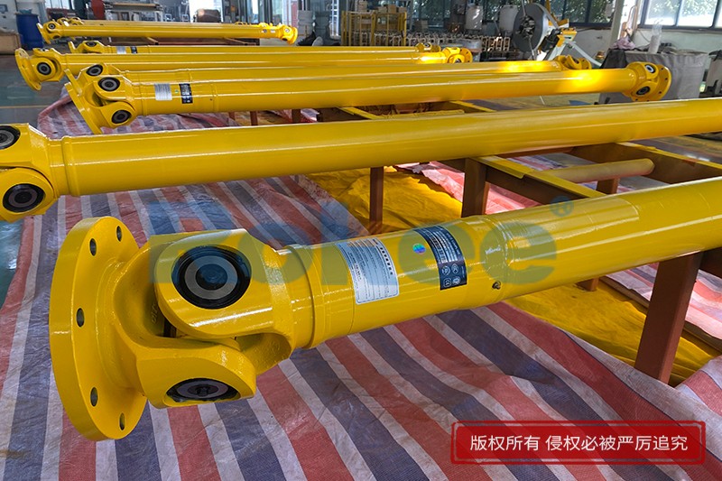
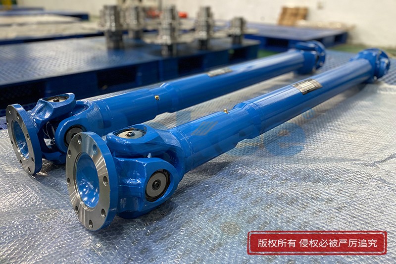
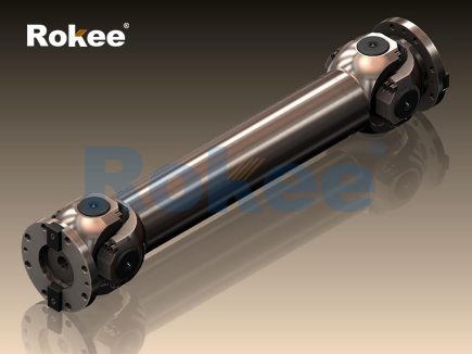
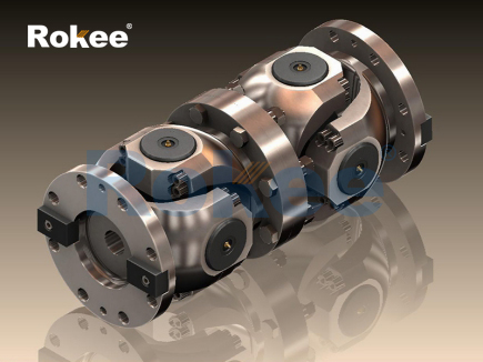
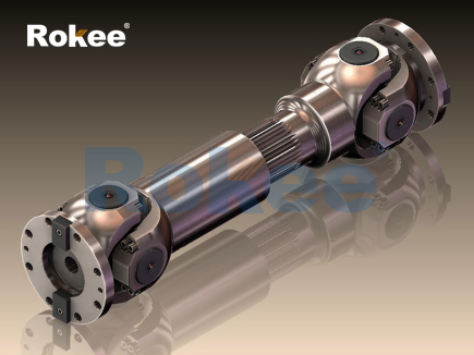
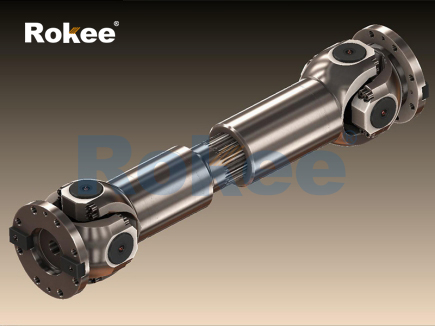
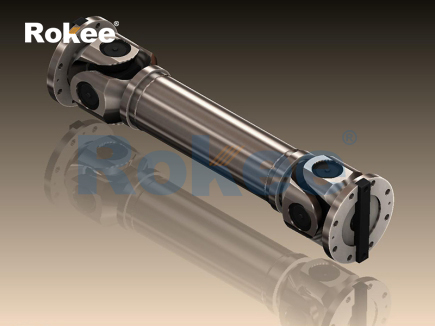
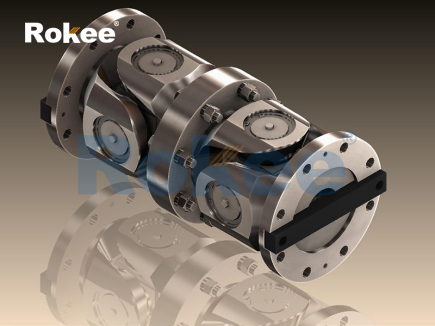
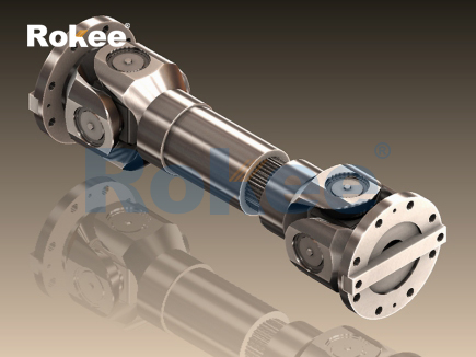
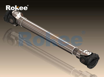
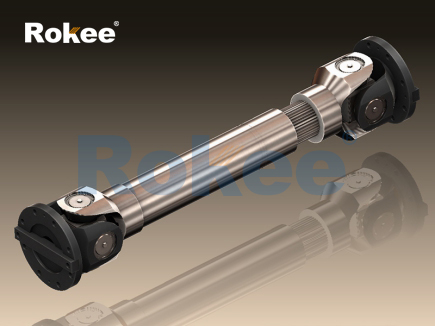
The telescopic drive shaft serves as a critical mechanical power transmission component designed to transfer rotational torque between two machine components while accommodating changes in axial distance during operation. At its core, the working principle relies on a sliding engagement structure that permits length adjustment without interrupting the steady flow of rotary force. The assembly generally consists of an outer tubular shaft and an inner splined shaft that fit tightly together, where machined splines on one part mesh with matching grooves on the other. These splines transmit torque through surface contact along their sides, while still allowing the inner shaft to slide longitudinally inside the outer tube when the relative position of connected equipment shifts. As the driving end rotates, the splined profile locks the two segments rotationally, ensuring both parts spin at identical angular velocity even as the overall shaft assembly extends or contracts. Small clearances between spline surfaces are carefully controlled to reduce friction during sliding movement, while retaining sufficient contact area to bear applied torque loads. Without this sliding capability, minor positional shifts between connected machinery would introduce bending stress, vibration, or component failure. The telescopic motion responds passively to relative displacement of the connected equipment, extending when mounting points move apart and retracting when they draw closer, all while maintaining continuous torque transmission. Lubrication applied to the spline contact surfaces reduces wear and prevents seizing during repeated extension and retraction cycles, preserving consistent performance over long operating periods. This fundamental combination of spline-based torque transfer and axial sliding forms the foundation of how telescopic drive shafts function in power transmission systems.
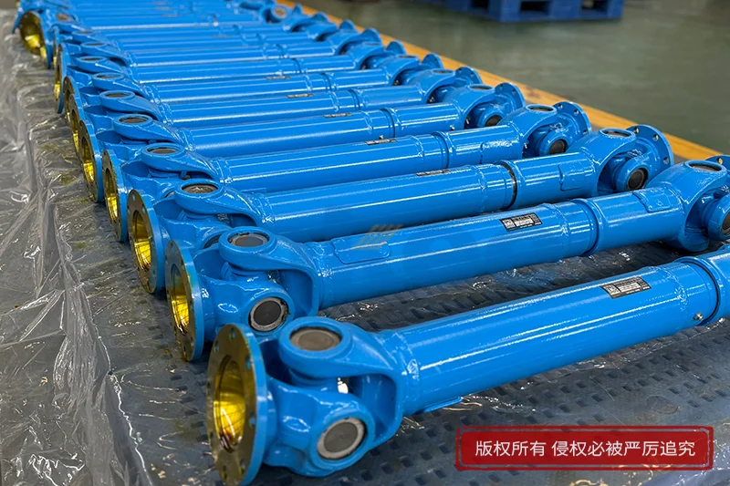
Material selection directly shapes the operating performance and durability of a telescopic drive shaft, as the components must balance high torsional strength with the ability to sustain repeated sliding contact between mating splines. The primary tubular sections and splined parts are manufactured from robust metallic materials that resist twisting deformation under torque loads, while also offering good wear resistance on the sliding spline surfaces. Heat treatment processes are commonly applied to spline regions to harden the outer layer of the material, lowering abrasion caused by continuous relative sliding between the inner and outer shaft segments. The core material remains tough beneath the hardened surface layer, helping the assembly absorb sudden impact loads that may occur during startup or fluctuating operating conditions. If the material lacked sufficient hardness on spline surfaces, repeated sliding would quickly wear away the spline profile, creating excessive backlash and reducing the accuracy of torque transmission. Conversely, overly brittle material would risk cracking under torsional shock even with proper surface hardening. The tube wall thickness is engineered to limit bending deflection when the shaft rotates, especially at higher rotational speeds, where imbalance or slight misalignment can amplify vibration. Material uniformity is also important to avoid localized stress concentrations that can develop along spline roots or tube transition areas. Every material choice supports the dual functional demands of the telescopic structure: reliable torque carrying capacity and smooth axial sliding movement across countless extension and retraction cycles throughout the service life of the component.
The spline connection, which forms the heart of the telescopic mechanism, operates by distributing torque evenly across multiple raised teeth and matching recesses arranged around the circumference of the shaft parts. Unlike simple keyed connections that concentrate load on a single contact surface, splines spread torsional force across many contact faces, reducing the pressure applied to any individual surface and allowing the assembly to handle larger torque values. Each spline tooth engages along its flank rather than its tip or root, so sliding movement along the axis does not interfere with rotational locking between the inner and outer shaft. When the driving component begins to turn, force pushes against the spline flanks, pulling the driven section to rotate in sync. As the distance between the two connected machines changes, the spline teeth slide within their corresponding grooves, changing the overall length of the shaft assembly while maintaining full contact on the load-bearing flanks. Minor geometric precision during manufacturing ensures that all spline teeth share the load nearly equally, preventing premature wear on a small number of overloaded teeth. Slight backlash between spline flanks accommodates lubricant film formation and thermal expansion, though excessive backlash would create rotational play and impact loads during direction reversals. Controlling the form and alignment of splines ensures that sliding motion remains smooth, and torque transfer stays stable whether the shaft is fully extended, partially retracted, or moving dynamically between these positions. This unique structural design separates axial freedom of movement from rotational locking to deliver the core benefit of telescopic drive shafts.
Sealing systems are integrated into telescopic drive shaft assemblies to protect the sliding spline interface from external contaminants and retain lubricant inside the working zone, which is essential for stable long-term operation. A flexible sealing element sits at the opening where the inner shaft slides into the outer tube, forming a close barrier around the moving shaft surface. As the shaft extends and retracts, the seal stays in constant contact with the outer surface of the inner splined shaft, blocking dust, moisture, fine particles, and debris from entering the spline engagement area. If foreign particles enter between the spline teeth, they act as abrasive media, accelerating surface scratching and wear that can degrade the spline profile over time. The seal also prevents the lubricating grease or oil from leaking out of the spline cavity, maintaining a continuous lubricating film between sliding surfaces. This lubricating film reduces metal-to-metal friction, lowers heat generation during sliding motion, and inhibits corrosion on the machined spline surfaces. The seal material must maintain elasticity across a range of operating temperatures, avoiding hardening or softening that would break the sealing contact. It also needs to withstand minor surface friction from the sliding shaft without rapid deterioration. While the seal permits axial movement of the inner shaft, it limits the entry of harmful environmental elements. Proper sealing reduces maintenance requirements and extends the usable life of the spline set by preserving the controlled lubrication environment required for the telescopic mechanism to function reliably.
Vibration and dynamic load management represent an important part of the working characteristics of telescopic drive shafts, since rotating power transmission components naturally encounter fluctuating forces during operation. When a telescopic drive shaft rotates, any slight angular misalignment between the driving and driven ends creates periodic dynamic loads that act on the spline interface and tubular sections. The sliding spline structure can absorb small axial dynamic displacements, but it cannot fully compensate for large angular misalignment, which may generate cyclic bending stress on the shaft tubes. As rotational speed increases, unbalanced mass within the shaft assembly produces centrifugal force that amplifies vibration, which can accelerate spline wear and loosen connected joints. Dynamic torque spikes, common during equipment startup, sudden load changes, or load reversals, create impact forces on spline flanks. The distributed load design of splines helps spread these transient torque loads, reducing peak stress on individual contact surfaces. Engineers design the tube geometry and spline dimensions to tune the natural frequency of the shaft assembly, avoiding resonant vibration conditions that could cause destructive deflection. During normal operation, the telescopic movement responds to slow axial positional changes, while rapid dynamic axial shocks are partially buffered by the lubricant film between spline surfaces. Understanding these dynamic behaviors allows for proper matching of the telescopic drive shaft to operating conditions, minimizing vibration, noise, and fatigue damage under variable load and speed cycles.
Installation alignment and operating displacement range define the practical working limits of a telescopic drive shaft, as the component is engineered to function within a designed range of extension and retraction. Before operation, the relative positions of the connected equipment are adjusted so that the telescopic shaft sits at a mid-range length under normal working conditions. This setup reserves enough travel distance for both extension and retraction when the mounting points move apart or draw closer during machine operation. If the shaft is installed near its fully extended limit, a small increase in separation can pull the spline teeth out of engagement, cutting off torque transmission and risking component damage. In the opposite case, installation at the fully retracted position allows no room for further compression, which creates compressive stress on the shaft assembly when mounting points move inward. Angular alignment between the two connection points is also critical. Even with the axial sliding capability, excessive angular offset imposes continuous bending loads on the tubular sections and uneven contact pressure across spline flanks. Operators must observe the maximum allowable sliding stroke of the assembly, which is determined by the physical length of the meshed spline section. As the shaft slides, the length of overlapping spline engagement changes; a larger overlap area provides higher torque capacity, while reduced overlap limits the maximum safe torque load. Adhering to the designed displacement range ensures the telescopic drive shaft transmits power safely through all expected positional changes of connected machinery.
Wear progression and performance degradation in telescopic drive shafts occur gradually over time, primarily at the spline contact surfaces, and directly affect how the assembly performs its dual roles of torque transfer and axial sliding. Continuous sliding and rotational contact wear away the fine machined profile of spline teeth. At the early stage of wear, material loss is minimal, and the shaft still maintains smooth sliding and consistent torque transmission, with only a small increase in rotational backlash. As wear accumulates, the clearance between mating spline flanks grows larger, creating noticeable play when torque direction reverses. This play generates impact loads each time the torque direction changes, further accelerating wear and producing noise and vibration during rotation. Inadequate lubrication or seal damage speeds up this wear process dramatically, as dry metal contact creates high friction and heat that can cause surface scoring or galling on spline surfaces. Heavy overload conditions can also deform spline teeth permanently, altering the contact geometry and preventing uniform load distribution. When wear reaches a critical level, the spline engagement can no longer support the rated torque, and unpredictable movement between the inner and outer shaft segments may appear. Regular inspection focuses on checking backlash, seal integrity, and spline surface condition, identifying wear before it impairs machine operation. Recognizing the pattern of wear helps maintain the reliable function of the telescopic drive shaft and prevents unexpected breakdowns in power transmission systems.
The application flexibility of telescopic drive shafts stems from their unique ability to combine rotary power transmission with controlled axial length adjustment, making them suitable for many mechanical systems where connected components shift relative to one another during operation. In many power transmission arrangements, the distance between the driving source and driven mechanism is not fixed; thermal expansion of machine frames, suspension movement, or positional adjustment of working parts all create changes in center distance. A rigid drive shaft cannot accommodate such movement and would transfer harmful axial forces into connected bearings and housings, leading to premature failure of adjacent parts. The telescopic structure eliminates this problem by sliding freely along the axis, absorbing positional variation without transmitting axial thrust loads between the two connection points. The shaft can adapt to steady, slow positional shifts as well as repeated cyclic extension and retraction cycles, as long as motion stays within the designed sliding stroke. Different configurations of spline profiles and tube constructions can be adapted for low-speed high-torque applications or higher-speed systems with moderate torque demands. Despite this flexibility, the component remains focused on axial compensation, and additional joint structures are required if large angular misalignment must also be managed. Across varied mechanical setups, the telescopic drive shaft provides a straightforward solution for power transmission under variable mounting distances. Its working principle of spline-coupled rotary locking paired with axial sliding continues to be a reliable mechanical approach for dynamic power transfer in many industrial and mobile mechanical systems.
- Tags:
- Telescopic Drive Shafts ,
- sandwich panel line ,
- sandwich panel machine
- pu sandwich panel machine
« Working Principle of Telescopic Drive Shafts » Latest Update Date: Oct 20, 2026
https://www.rokeecoupling.net/blog/working-principle-of-telescopic-drive-shafts.html