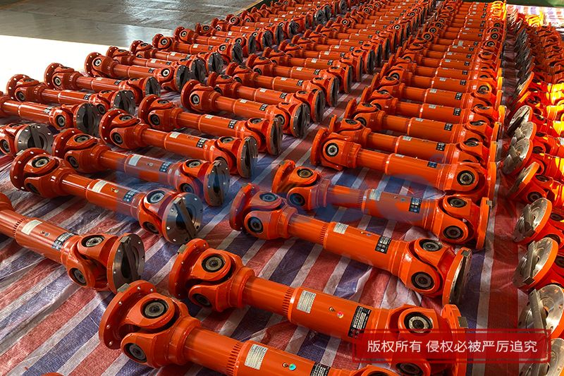
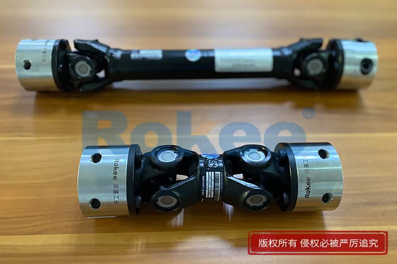
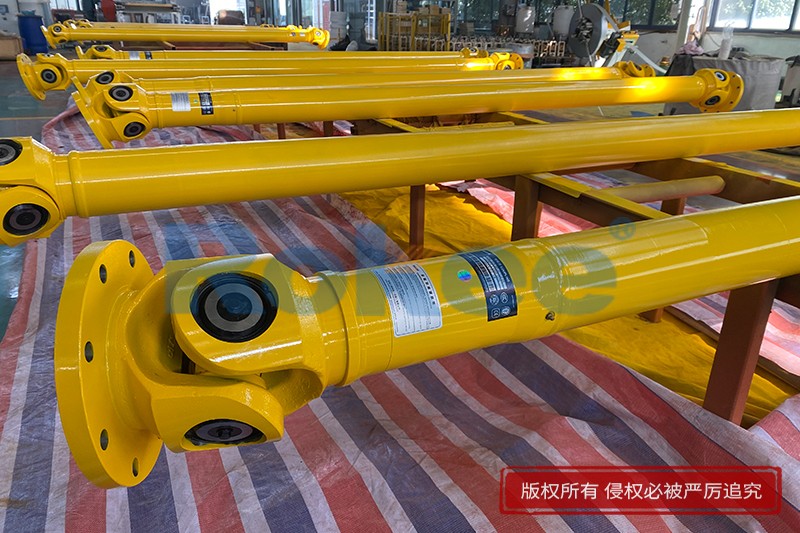
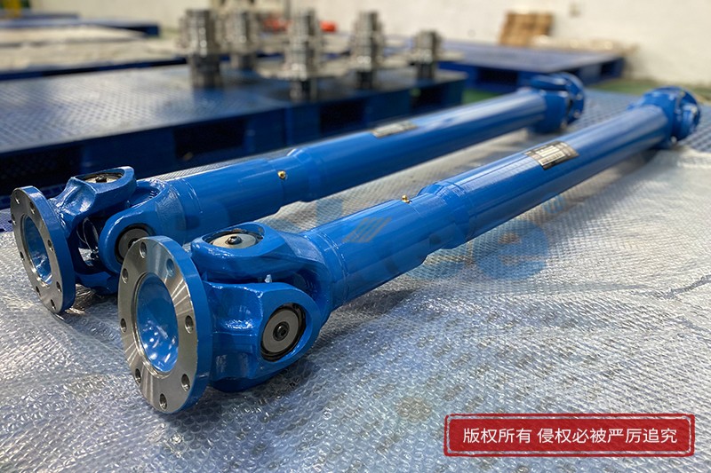
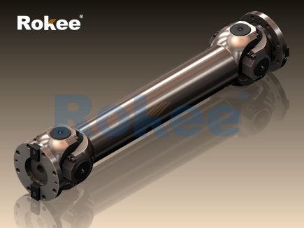
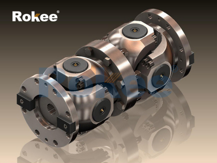
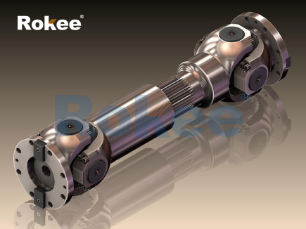
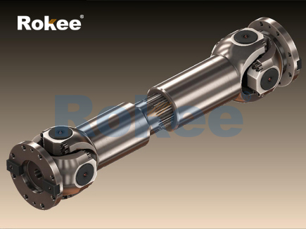
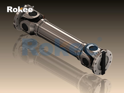
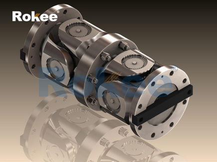
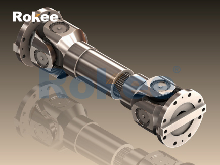
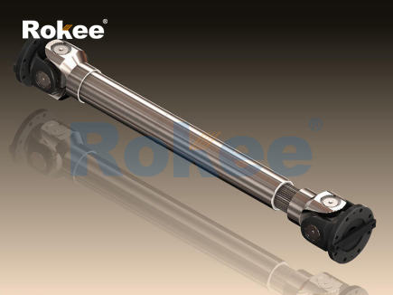
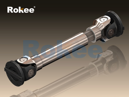
The universal shaft, also widely known as the universal joint shaft, serves as a mechanical transmission component designed to transfer rotational torque between two shafts that are not aligned along a single straight axis. At its core, the working principle relies on flexible connecting structures that accommodate angular offsets between driving and driven ends while maintaining continuous rotation. A basic universal shaft assembly contains cross-shaped hinge parts, yoke forks and connecting sleeves, where the cross piece acts as the pivotal joint linking two fork components. When the driving shaft spins, it pushes the cross hinge to revolve, and the cross then transmits motion to the connected driven yoke and shaft. This unique hinge structure permits a certain angle between the two shafts, allowing the transmission system to operate even when shaft positions shift during equipment running. It is critical to recognize that a single universal joint cannot deliver constant angular velocity transmission. If only one joint is used, the rotational speed of the driven shaft fluctuates within each rotation cycle as the deflection angle increases, creating periodic speed variation and vibration. This inherent characteristic limits the application range of single-joint universal shafts, especially in systems requiring smooth and stable rotation. Engineers commonly pair two universal joints together to counteract this speed fluctuation effect, arranging the joints with matched deflection angles to balance out the uneven speed output. The basic movement of the universal shaft depends entirely on the geometric motion of the hinge, without relying on hydraulic or pneumatic power sources, which makes the component simple in fundamental mechanical logic.
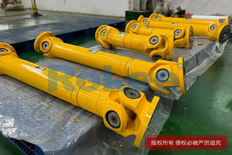
The geometric relationship of the hinge directly defines the motion features of the universal shaft during torque transmission. When an angular deviation exists between the input shaft and output shaft, the cross member swings within the plane of the yoke forks with every full rotation. At specific rotational positions, the effective lever length of torque transmission changes continuously, which leads to the variable speed phenomenon of the driven shaft. To understand this movement, imagine the driving yoke rotating around its central axis and driving the cross to tilt back and forth following the preset deflection angle. As the cross turns, the two sets of bearing surfaces between cross and yoke slide and roll against each other, transferring force while allowing angular movement. The magnitude of speed fluctuation is closely related to the operating angle between shafts; larger deflection angles create more dramatic changes in instantaneous speed, which brings extra alternating stress to all moving parts. Such alternating stress can induce mechanical vibration, noise and fatigue wear if not properly controlled. When two universal joints are assembled in series, the installation orientation becomes the key factor to eliminate speed irregularity. The yoke forks on the intermediate shaft must be placed in the same plane, and the deflection angle of the first joint should equal the deflection angle of the second joint. Under this arrangement, the speed variation produced by the first joint gets offset by the second joint, and the final output shaft can rotate at a steady constant speed matching the input shaft.
Torque transfer and force distribution form another important part of the universal shaft working principle. When rotational torque passes through the universal shaft, force is distributed to the contact surfaces of the cross pins and the inner surface of the yoke fork bearings. These contact surfaces bear combined loads including tangential torque force and radial force generated by the angular deflection. The force direction changes constantly as the shaft rotates, producing cyclic loading on the pin and bearing assemblies. This cyclic load causes repeated compression and slight sliding on the contact areas, which is why lubrication plays an essential role in normal operation. Without sufficient lubricant, friction between metal contact surfaces rises rapidly, accelerating surface abrasion and increasing the risk of seizure during continuous rotation. The universal shaft can adapt to changing working distances in some cases, and certain designs include telescopic sleeve structures to compensate for axial displacement between the connected shafts. The telescopic section slides along spline surfaces, permitting small changes in shaft length while torque keeps transferring. It is worth noting that axial sliding movement adds another source of friction and wear, so the spline area also needs reliable lubrication. The whole component bears both static torque load and dynamic impact load during startup, speed adjustment or sudden load changes. Excessive impact load may deform the cross pins or crack the yoke forks, which will break the continuity of power transmission.
The vibration and dynamic response of universal shafts arise from the variable-speed motion and alternating forces inside the joint structure. Even when double universal joints are properly arranged to achieve constant output speed, minor manufacturing deviations, assembly errors or slight angle mismatch will still leave residual periodic excitation force. This excitation force propagates through the connected shafts and spreads to the supporting structure of the whole mechanical system, creating vibration and resonant noise under specific rotating speeds. The mass distribution of rotating parts also influences dynamic performance. The cross member and yoke forks rotate around offset axes, generating centrifugal force when the universal shaft spins. If the rotating assembly lacks dynamic balance, centrifugal force grows with the square of rotational speed and amplifies vibration at high working speeds. Vibration not only reduces operation comfort but also accelerates fatigue damage of metal parts. Repeated cyclic stress concentrates at the root of yoke forks and the neck of cross pins, which are common failure positions for universal shafts. In practical use, operators need to keep the deflection angle within the recommended range, because excessive angles will greatly increase excitation force and shorten service life. Dynamic analysis of universal shafts focuses on studying how rotational speed, deflection angle and component mass interact to affect vibration amplitude, helping to optimize the structural design and operating parameters.
Material deformation and fatigue failure mechanisms accompany the working process of universal shafts under continuous cyclic loads. All metal components experience tiny elastic deformation when torque is applied. The cross pins bend slightly under transmitted torque, and the yoke forks deform outward at their open ends. When the load is removed, most elastic deformation recovers, but long-term repeated loading creates micro cracks at stress concentration points. These micro cracks slowly expand with each rotation cycle until they develop into macroscopic cracks, eventually leading to component fracture. The contact area between cross pins and bearings suffers contact fatigue. Small pits appear on the metal surface after repeated rolling and sliding contact, a phenomenon known as pitting corrosion. As pits accumulate, the contact surface becomes rough, friction rises, and bearing damage accelerates. Temperature also affects this process. Frictional heat generated at the joint raises the local temperature of contact surfaces, reducing material hardness and accelerating wear. Heavy load conditions worsen heat accumulation, while low speed and light load produce less heat and slower fatigue progression. Designers select suitable metal materials and carry out surface strengthening treatments to improve resistance against contact fatigue and bending fatigue, extending the usable cycle of universal shafts under normal working conditions.
Lubrication and sealing systems support the stable working principle of universal shafts by controlling friction and preventing contaminant intrusion. Lubricant fills the narrow clearance between cross pins and bearing sleeves, forming a thin oil film that separates metal surfaces. This oil film reduces direct metal-to-metal contact, lowers friction coefficient and dissipates part of the frictional heat produced during rotation. When the universal joint swings continuously at an angle, the relative movement between pins and bearings constantly squeezes and circulates the lubricant inside the bearing cavity. The sealing elements fitted at the ends of bearing housings block dust, moisture and fine abrasive particles from entering the lubrication space. If seals become worn or damaged, external impurities mix with lubricant, turning it into an abrasive paste that scratches the contact surfaces. Water contamination can also trigger corrosion on pins and bearing inner surfaces, weakening component strength. Lubricant performance gradually declines over operating time due to thermal aging and contamination. Degraded lubricant loses the ability to form a complete oil film, and friction and wear increase sharply. Regular maintenance includes replenishing or replacing lubricant and inspecting sealing components, ensuring the joint can keep moving freely without excessive friction or corrosion damage.
Installation conditions affect whether a universal shaft can function according to its designed working principle. Alignment status is the primary factor, covering both angular offset and axial position of the two connected shafts. When installing a double universal shaft set, improper orientation of intermediate yoke forks destroys the speed compensation effect, bringing back obvious speed fluctuation and vibration. Too large a working angle increases alternating stress and friction heat, while too small an angle may limit the flexible compensation function that the universal shaft is meant to provide. Axial misalignment imposes extra bending load on cross pins and forks, accelerating fatigue damage. Mounting stiffness of the bearing supports also matters. If the supporting structures connected to the universal shaft are too flexible, they will deform under torque load and change the actual deflection angle during operation, introducing unexpected dynamic excitation. Preload on bearing assemblies influences internal clearance. Too much preload increases friction and heat, while insufficient preload creates clearance and impact during load reversal. Operators must check the assembly after installation, verifying rotation flexibility and confirming there is no abnormal jamming or collision between moving parts. Proper installation preserves the designed geometric motion relationship, allowing the universal shaft to transmit torque smoothly while compensating for shaft misalignment as intended.
The application boundaries of universal shafts are determined by the limits of their working principle. The flexible hinge structure enables torque transmission with angular compensation, yet it cannot handle unlimited deflection angles, rotational speeds or torque values. At extremely high rotating speeds, centrifugal force and dynamic vibration become prominent, and even well-balanced universal shafts face higher risk of fatigue failure. When torque exceeds the bearing capacity of cross pins and yoke forks, permanent plastic deformation or sudden fracture may occur. The joint also has a limit for angular compensation; once the deflection angle goes beyond the feasible range, the movement of cross and yoke becomes constrained, and transmission will jam. In systems requiring ultra-precise rotational positioning, the small backlash existing inside hinge joints may introduce minor rotational clearance that affects positioning accuracy. Despite these limitations, universal shafts remain widely used for mechanical power transmission where connected shafts cannot maintain perfect coaxial alignment. Their simple mechanical principle, compact structure and ability to accommodate dynamic shaft position changes make them a reliable choice in many rotating transmission systems. Understanding the full working principle helps users choose appropriate structural forms, set reasonable operating parameters and carry out targeted maintenance, to achieve stable and long-lasting power transmission through universal shafts.
- Tags:
- Universal Shaft Couplings ,
- Universal Shafts ,
- Universal Shaft Joints ,
- sandwich panel line ,
- sandwich panel machine
- pu sandwich panel machine
« Working Principle of Universal Shafts » Latest Update Date: Oct 20, 2026
https://www.rokeecoupling.net/blog/working-principle-of-universal-shafts.html