Barrel couplings drawing is a fundamental and precise technical process that serves as the bridge between design concept and practical manufacturing of barrel couplings, which are specialized mechanical components widely used for torque transmission and shaft alignment in various rotational systems. These drawings are not merely simple sketches but detailed, standardized documents that encapsulate all critical information required to produce, assemble, and inspect barrel couplings, ensuring their compatibility, performance, and durability in diverse industrial applications. The accuracy and completeness of barrel couplings drawing directly determine the functionality of the final product, as even minor discrepancies in dimensions, tolerances, or structural details can lead to assembly failures, reduced efficiency, or even safety hazards in high-load operating environments. As such, mastering the principles, techniques, and best practices of barrel couplings drawing is essential for engineers, designers, and manufacturing professionals involved in the production and application of these vital mechanical components.

At its core, barrel couplings drawing is grounded in the principles of mechanical drafting, which emphasize clarity, precision, and standardization. Every line, dimension, and note on the drawing must be intentionally placed to convey exact information without ambiguity, as the drawing serves as a universal language between design, production, and quality control teams. Unlike generic mechanical drawings, barrel couplings drawing requires a deep understanding of the unique structural characteristics and functional requirements of barrel couplings, which typically consist of a cylindrical body—often referred to as the “barrel”—integrated with cavities, lips, or wings that facilitate torque transmission and shaft connection. The cylindrical geometry of the barrel is a defining feature, ensuring uniform stress distribution, enhancing load-bearing capacity, and improving fatigue resistance, all of which must be accurately reflected in the drawing to ensure the final product meets performance expectations.
Before initiating the drawing process, it is crucial to conduct a comprehensive analysis of the application requirements for the barrel coupling. This includes determining the torque capacity, radial and axial load requirements, misalignment compensation needs, operating environment (such as temperature, pressure, and corrosive conditions), and compatibility with the shafts it will connect. For example, barrel couplings used in crane hoisting mechanisms must be designed to transmit high torques and withstand large radial loads while compensating for minor angular misalignments caused by structural deflection or mounting inaccuracies, whereas those used in automotive drivetrains may prioritize vibration damping and flexibility. This application-specific analysis directly informs every aspect of the drawing, from material selection and structural design to dimensioning and tolerance specifications.
Material selection is a key consideration that influences both the design and drawing of barrel couplings, and this information must be clearly indicated on the drawing. Common materials used for barrel couplings include high-strength carbon steel, alloy steel, stainless steel, and in some cases, lightweight materials such as aluminum alloys for applications where weight reduction is critical, such as aerospace systems. The material choice is determined by the operating conditions: for instance, stainless steel is preferred for applications in corrosive environments like chemical processing or marine systems, while alloy steel is used for high-torque applications in heavy machinery and steel production. The drawing must specify the material grade, as well as any heat treatment requirements—such as quenching and tempering to enhance hardness and durability—or surface treatments like galvanizing or coating to improve corrosion resistance. These details are essential for the manufacturing team to select the appropriate processing methods and ensure the material properties meet the design specifications.
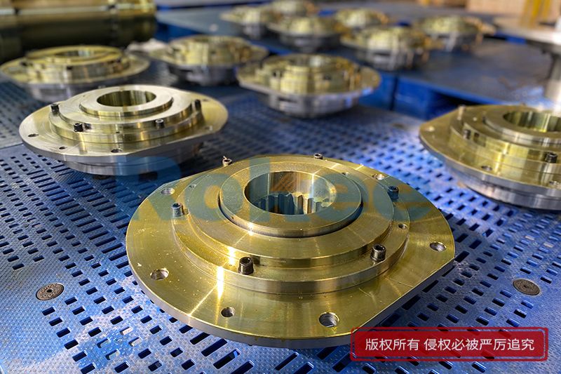
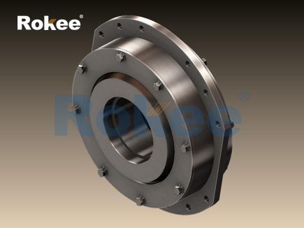
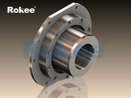
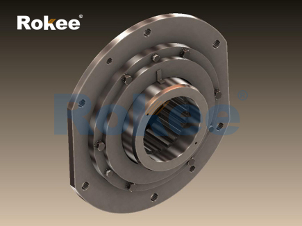
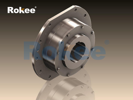
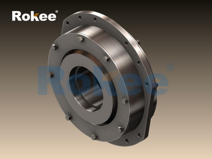
The structural design of barrel couplings varies based on their type and application, and the drawing must accurately represent these structural details. There are several common types of barrel couplings, each with distinct features that must be clearly depicted. Rigid barrel couplings are designed for applications where precise shaft alignment is maintained, featuring a solid cylindrical body often integrated with flanges or splines for secure shaft connection; their drawings must emphasize the rigidity of the structure and the precision of the connection points. Flexible barrel couplings, on the other hand, incorporate elastic elements such as rubber or metal membranes to accommodate angular, parallel, or axial misalignments and dampen vibrations, and their drawings must detail the elastic components, their placement, and the range of misalignment they can compensate for. Clamping barrel couplings utilize split sleeves or adjustable collars for easy installation and maintenance, and their drawings must show the split design, clamping mechanism, and adjustment points to ensure proper assembly.
Another critical aspect of barrel couplings drawing is dimensioning, which involves specifying the exact size of every structural feature, including the diameter and length of the barrel, the size and position of cavities and lips, the dimensions of flanges or splines, and the location of mounting holes. Dimensioning must follow established mechanical drafting standards to ensure consistency and avoid misinterpretation. It is essential to distinguish between critical dimensions—those that directly affect the coupling’s performance and compatibility—and non-critical dimensions, which can have slightly wider tolerances. For example, the inner diameter of the barrel, which fits over the shaft, is a critical dimension that must be precisely specified to ensure a proper fit, while the outer diameter may have a wider tolerance if it does not affect the coupling’s functionality or assembly. The drawing must also include dimensional chains, which show the relationship between related dimensions, to ensure that the cumulative tolerance does not exceed acceptable limits.
Tolerance specification is another vital component of barrel couplings drawing, as it defines the acceptable variation in dimensions during manufacturing. Tolerances are determined based on the functional requirements of the coupling: critical features such as shaft fits, torque transmission surfaces, and alignment points require tight tolerances to ensure precision, while non-critical features can have more relaxed tolerances to reduce manufacturing costs. It is important to avoid over-specifying tolerances, as this can increase production costs unnecessarily without providing any additional benefit. For example, a tolerance of ±0.01mm may be required for the inner diameter of the barrel to ensure a secure fit with the shaft, while the length of the barrel may have a tolerance of ±0.1mm. The drawing must clearly indicate tolerances using standard notation, either directly next to the dimension or in a tolerance block, to ensure the manufacturing team understands the precision requirements.
In addition to dimensions and tolerances, barrel couplings drawing must include detailed views to fully represent the coupling’s structure. This typically includes a front view, side view, and cross-sectional view, which shows the internal structure of the barrel, such as cavities, lips, and any internal components like elastic elements or clamping mechanisms. For complex designs, additional views such as detailed views of specific features, exploded views to show assembly sequence, or auxiliary views to represent angled features may be necessary. These views must be arranged in a logical manner, following the principles of orthographic projection, to ensure that all structural details are clearly visible and easy to interpret. The use of section lines in cross-sectional views helps to distinguish between different parts of the coupling and highlight internal features.
Surface finish requirements are also an important part of barrel couplings drawing, as they affect the coupling’s performance, durability, and compatibility with other components. The surface finish is specified using roughness parameters, such as Ra (arithmetic mean deviation), which indicate the smoothness of the surface. For example, the inner surface of the barrel that contacts the shaft may require a smooth surface finish (Ra ≤ 1.6 μm) to reduce friction and wear, while the outer surface may have a coarser finish (Ra ≤ 6.3 μm) if it does not come into contact with other components. The drawing must clearly indicate the surface finish requirements for each critical surface, either directly on the view or in a note, to ensure the manufacturing team uses the appropriate processing methods—such as grinding, turning, or polishing—to achieve the desired finish.
Assembly and installation instructions are often included in barrel couplings drawing to guide the manufacturing and installation teams. These instructions may include details on the sequence of assembly, the use of fasteners (such as bolts or screws) and their torque requirements, the application of lubrication (if necessary), and any special handling precautions. For example, clamping barrel couplings may require specific torque values for the clamping screws to ensure a secure fit without damaging the shaft or the coupling itself, and this information must be clearly stated in the drawing. Installation instructions may also include guidance on aligning the coupling with the shafts, checking for misalignment, and verifying the fit before operation. These instructions are critical for ensuring that the coupling is assembled and installed correctly, which directly affects its performance and service life.
Quality control requirements are another essential component of barrel couplings drawing, as they define the standards that the final product must meet. These requirements may include inspection methods, such as dimensional measurement using calipers, micrometers, or coordinate measuring machines (CMM), surface finish testing using a profilometer, and functional testing to verify torque transmission, misalignment compensation, and load-bearing capacity. The drawing may also specify acceptance criteria, such as the maximum allowable deviation from critical dimensions, the minimum surface finish required, and the performance thresholds for functional tests. These quality control requirements ensure that the manufactured barrel couplings meet the design specifications and are suitable for their intended application.
When creating barrel couplings drawing, it is important to avoid common mistakes that can lead to misinterpretation or manufacturing errors. One common mistake is over-reliance on absolute precision, which involves specifying unnecessarily tight tolerances for non-critical features, increasing manufacturing costs and complexity. Another mistake is inadequate view representation, such as missing cross-sectional views or detailed views of critical features, which can make it difficult for the manufacturing team to understand the structure of the coupling. Poor dimensioning practices, such as inconsistent dimensioning standards, missing critical dimensions, or dimensioning the same feature multiple times, can also lead to confusion and errors. Additionally, vague or ambiguous notes, such as “surface must be smooth” without specifying a roughness parameter, can result in inconsistent surface finishes and performance issues.
To avoid these mistakes, it is essential to follow best practices in barrel couplings drawing. This includes using standardized drafting symbols and notation, ensuring that all views are clear and complete, and specifying dimensions and tolerances based on functional requirements rather than arbitrary precision. It is also important to review the drawing thoroughly before finalizing it, checking for errors, inconsistencies, and omissions. Collaboration between design, manufacturing, and quality control teams during the drawing process can help identify potential issues early and ensure that the drawing meets the needs of all stakeholders.
The application of barrel couplings drawing extends across a wide range of industries, each with unique requirements that influence the drawing process. In the lifting and hoisting industry, for example, barrel couplings are used to connect the gearbox output shaft with the wire drum in cranes and hoists, requiring drawings that emphasize high torque transmission, radial load capacity, and misalignment compensation. The drawings for these couplings must detail the structure that allows the hub to oscillate with respect to the sleeve, compensating for angular misalignments and absorbing axial displacements, as well as the wear indicators that allow for inspection without disassembly. In the automotive industry, barrel couplings are used in drivetrains to transfer power while dampening engine vibrations, requiring drawings that focus on flexibility and vibration damping, with detailed representations of elastic elements and their mounting points.
In the aerospace industry, barrel couplings are used in aircraft landing gear and control systems, requiring lightweight, high-strength designs that must be accurately represented in drawings with tight tolerances and detailed material specifications. The drawings for these couplings must account for the extreme operating conditions, such as high temperatures and pressures, and ensure that the coupling can withstand the stresses of flight. In the manufacturing industry, barrel couplings are used to synchronize conveyor belts and robotic arms in automated assembly lines, requiring drawings that emphasize precision and reliability, with clear details on the connection points and alignment features.
Advancements in computer-aided design (CAD) technology have significantly transformed barrel couplings drawing, making the process more efficient, accurate, and flexible. CAD software allows designers to create 3D models of barrel couplings, which can be rotated and viewed from any angle to verify the structure and identify potential design issues before creating 2D drawings. 3D models also facilitate the integration of the coupling with other components in the system, ensuring compatibility and proper alignment. CAD software also includes tools for automatic dimensioning, tolerance specification, and surface finish notation, reducing the risk of human error and ensuring consistency with drafting standards. Additionally, CAD drawings can be easily modified, updated, and shared with manufacturing and quality control teams, improving collaboration and reducing the time required to bring the product to market.
Despite the advantages of CAD technology, the principles of barrel couplings drawing remain unchanged: clarity, precision, and standardization are still the foundation of a high-quality drawing. Designers must still have a deep understanding of the structural and functional requirements of barrel couplings, as well as the manufacturing processes used to produce them, to create accurate and useful drawings. CAD software is a tool that enhances the drawing process, but it cannot replace the expertise and judgment of a skilled designer.
In conclusion, barrel couplings drawing is a critical technical process that plays a vital role in the design, manufacturing, and application of barrel couplings. It requires a combination of technical knowledge, drafting skills, and attention to detail, as well as an understanding of the unique requirements of the application and the manufacturing processes. A well-executed barrel couplings drawing provides clear, accurate, and comprehensive information that guides the production team in creating a high-quality product that meets performance expectations and safety standards. By following best practices, avoiding common mistakes, and leveraging advanced CAD technology, designers can create drawings that are efficient, reliable, and compatible with the needs of diverse industries. As industrial systems become more complex and demanding, the importance of precise and detailed barrel couplings drawing will only continue to grow, ensuring that barrel couplings remain a reliable and essential component in torque transmission and shaft alignment applications worldwide.
- Tags:
- Barrel Couplings ,
- sandwich panel line ,
- sandwich panel machine
- pu sandwich panel machine
« Barrel Couplings Drawing » Latest Update Date: May 9, 2026
https://www.rokeecoupling.net/blog/barrel-couplings-drawing.html