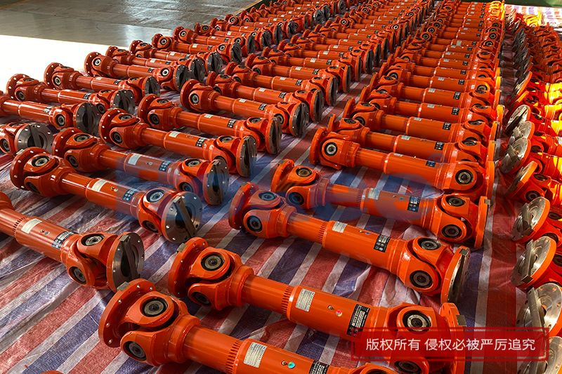
As a fundamental flexible transmission component widely adopted in mechanical engineering, automotive transmission systems, agricultural machinery and heavy industrial equipment, the cardan shaft serves as a critical connecting part to transmit torque and rotational motion between two misaligned shafts. Unlike rigid drive shafts that can only work efficiently under complete coaxial conditions, cardan shafts are designed to accommodate angular deflection, axial displacement and minor radial offset between driving and driven ends during continuous operation. This adaptive flexibility enables smooth power transmission even when the relative position of connected mechanical components changes dynamically due to vibration, road surface fluctuation or structural deformation. Derived from the classic universal joint mechanism first studied by medieval mechanical researchers, cardan shafts have undergone continuous structural upgrading and dimensional optimization over hundreds of years. Diversified structural variants have been developed to match varying working speeds, load levels, deflection angles and installation space constraints. A comprehensive understanding of different cardan shaft classifications, structural characteristics, functional advantages and applicable working conditions is essential for mechanical design optimization, reasonable component selection and long-term operational stability of overall transmission systems. This article elaborates on mainstream cardan shaft types classified from multiple dimensional perspectives, explains their inherent working characteristics, compares their functional pros and cons, and illustrates their targeted application ranges in modern mechanical industries.

Before exploring specific classifications of cardan shafts, it is necessary to clarify the universal working principle shared by all cardan shaft designs, as the core mechanical logic remains consistent across all variants. The basic assembly of a standard cardan shaft consists of universal joints, intermediate shaft tubes, bearing assemblies and telescopic spline structures. The core power transmission unit is the cross universal joint, composed of two fork-shaped yokes and a central cross spider with four trunnions. Each trunnion of the cross spider is fitted with compact needle roller bearings to reduce rotational friction and bear alternating torsional loads during operation. When the driving shaft rotates continuously, motion and torque are transferred to the cross spider via one yoke, and the cross spider further drives the driven yoke and connected driven shaft to rotate synchronously. An unavoidable inherent mechanical feature exists in single universal joint structures: non-uniform angular velocity transmission. When a deflection angle exists between the driving shaft and driven shaft, the instantaneous rotating speed of the driven shaft fluctuates periodically within one full rotation cycle, even if the driving shaft maintains a constant rotating speed. The amplitude of this speed fluctuation increases synchronously with the growth of the shaft deflection angle, bringing periodic torsional vibration, mechanical impact and power transmission instability. All type differences of cardan shafts are essentially targeted structural improvements to compensate for this inherent defect, adapt different load demands or fit limited installation environments, forming a complete product spectrum covering light-duty to ultra-heavy-duty, low-speed to high-speed working scenarios.
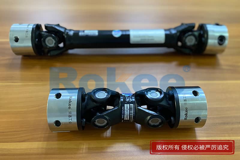
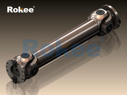
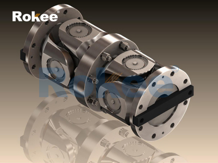
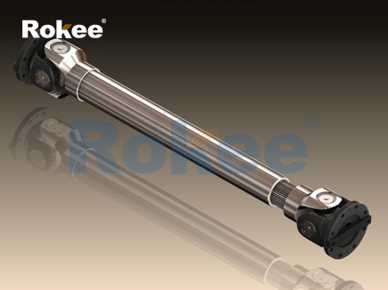
The most common classification method divides cardan shafts according to the number of built-in universal joints, namely single-joint cardan shafts and double-joint cardan shafts, which are the most basic structural divisions determining core transmission performance. Single-joint cardan shafts are the simplest structural form, equipped with only one cross universal joint matched with a short integrated shaft body. This type features minimal overall length, fewer assembly components and low manufacturing complexity, requiring little installation space during equipment assembly. Nevertheless, it cannot eliminate the non-uniform velocity transmission defect of individual universal joints fundamentally. For this reason, single-joint cardan shafts are restricted to working conditions with small stable deflection angles, usually below 10 degrees, low rotating speed and light cyclic loads. Typical application scenarios include auxiliary transmission structures of small agricultural machinery, low-power conveyor connecting components and simple manual mechanical transmission mechanisms where slight vibration and speed fluctuation will not affect overall equipment operation. It is not suitable for high-speed rotating systems or power transmission assemblies requiring smooth and stable torque output, as long-term operation will generate accumulated vibration, accelerate bearing wear and shorten the service life of matching transmission parts. In contrast, double-joint cardan shafts add a middle intermediate shaft and a second universal joint based on the single-joint structure, forming a series-connected dual universal joint layout. Through standardized installation angle matching during assembly, the periodic speed fluctuation generated by the first universal joint can be completely counteracted by the reverse speed fluctuation produced by the second universal joint. This structural design realizes approximate constant-velocity overall power transmission without eliminating the flexible deflection compensation capability of universal joints. Double-joint cardan shafts can adapt to a maximum deflection angle ranging from 30 degrees to 45 degrees, covering most dynamic position changes generated by chassis suspension vibration in mobile machinery. Currently, this type occupies the largest market share in practical applications, widely used in vehicle transmission systems, medium-sized engineering machinery and general industrial transmission lines.
Based on internal joint structural differences, cardan shafts can be further split into cross-type cardan shafts and constant-velocity ball-type cardan shafts, which differ greatly in motion mode, deflection adaptability and high-speed operation performance. Cross-type cardan shafts adopt traditional cross spider universal joints as core transmission units, retaining mature and simple mechanical structures with strong impact resistance and excellent heavy-load bearing capacity. The manufacturing process of cross-type joints is highly mature, with low maintenance difficulty and convenient replacement of vulnerable wearing parts such as needle roller bearings and cross spiders. However, restricted by the spatial motion track of cross components, this type still retains minor residual speed fluctuation even with double-joint layout, and operating noise rises obviously when the deflection angle exceeds 35 degrees. Constant-velocity ball-type cardan shafts replace cross spiders with precision ball cage structures and steel ball transmission pairs. Steel balls roll along preset curved raceways inside joint housings during power transmission, realizing completely constant-velocity transmission regardless of deflection angles between connected shafts. This design eliminates torsional vibration and rotating noise fundamentally, making ball-type cardan shafts perfectly suitable for high-speed rotating working conditions and scenes requiring extremely smooth power output. Meanwhile, ball-type joints support a larger single-time deflection angle up to 50 degrees, showing better flexibility for drastic dynamic position changes. The main limitation lies in weaker impact resistance compared with cross-type structures; precision raceways and steel balls are vulnerable to surface damage under sudden heavy impact loads, and overall maintenance costs are higher due to higher assembly precision requirements. In practical matching, cross-type cardan shafts are prioritized for heavy-load, frequent impact and medium-speed working environments, while ball-type cardan shafts are more suitable for high-speed, low-impact and high-stability demanded transmission systems.
In view of actual load-bearing demands in industrial production and mobile machinery, cardan shafts are also categorized into light-duty, medium-duty, heavy-duty and ultra-heavy-duty types according to torsional strength, structural component size and material processing standards. Light-duty cardan shafts adopt thin-wall hollow shaft tubes, standard small-size cross joints and common quenched alloy steel materials. They are optimized for lightweight design with small overall volume and low rotational centrifugal force, matching low-torque and continuous steady operation conditions such as small household mechanical equipment and miniature automated production lines. Medium-duty cardan shafts are the most versatile type, adopting conventionally thickened shaft tubes and enhanced bearing assemblies, balancing structural weight, torsional rigidity and manufacturing cost comprehensively. They perfectly adapt to most standard road vehicles and general engineering machinery, coping with conventional alternating loads and occasional impact loads in daily operation. Heavy-duty cardan shafts apply integral forged shaft bodies, enlarged cross joint components and reinforced flange connecting structures, with all key parts undergoing integral quenching and tempering heat treatment to improve material fatigue resistance. This type is designed for long-term heavy-load circulation and frequent start-stop working states, commonly equipped on large construction machinery, bulk material transport equipment and metallurgical transmission equipment running in harsh environments. Ultra-heavy-duty cardan shafts represent the highest load level, adopting solid alloy steel shaft segments and oversized reinforced universal joints, capable of bearing extreme instantaneous torsional impact and long-term high-amplitude alternating loads. They are exclusively applied in large mining machinery, heavy metallurgical rolling equipment and large port handling machinery, where ordinary cardan shafts will suffer rapid fatigue fracture under extreme working loads. It is worth noting that load grade selection must strictly match actual operating torque; over-specification will cause unnecessary weight increase and energy consumption, while under-specification will lead to premature structural failure and system shutdown.
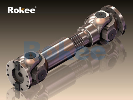
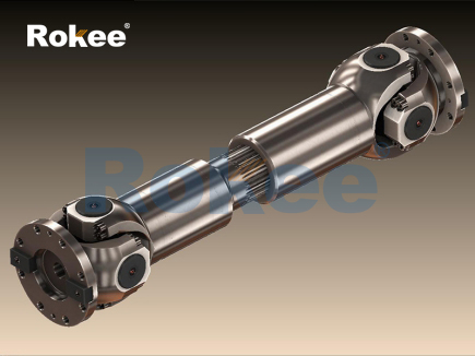
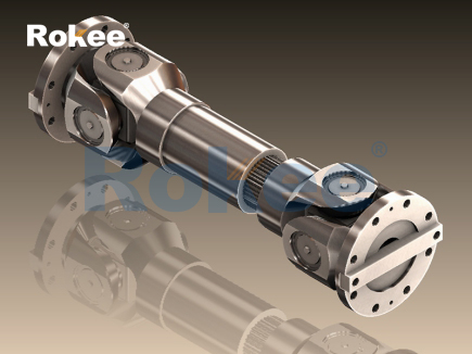
Another practical classification standard focuses on axial adaptive structures, dividing cardan shafts into fixed-length cardan shafts and telescopic cardan shafts. Fixed-length cardan shafts have integrated non-adjustable shaft bodies with fixed overall installation dimensions. They feature higher overall structural rigidity and better dynamic balance performance during high-speed rotation, free from additional vibration caused by telescopic structure clearance. Nevertheless, they cannot compensate axial distance changes between driving and driven ends. Once axial displacement occurs during equipment operation, additional tensile or compressive stress will act on the shaft body and universal joints, accelerating component fatigue damage. Therefore, fixed-length cardan shafts are only used in closed transmission systems with completely fixed relative positions of two shafts, such as sealed industrial gearbox internal transmission assemblies. Telescopic cardan shafts add spline telescopic pairs inside intermediate shaft segments, including internal spline sleeves and external spline shafts that can slide relatively along the axial direction. This structure actively compensates real-time axial distance changes caused by equipment vibration, component thermal expansion and mechanical structure deformation during operation, eliminating extra axial stress effectively. Most cardan shafts used in mobile vehicles and movable engineering machinery adopt telescopic structures to adapt to chassis jitter and suspension displacement during travelling. To guarantee transmission stability while retaining telescopic capability, spline pairs are filled with high-viscosity lubricating grease and equipped with integrated dustproof sealing sleeves, preventing abrasive particles from entering matching clearances and avoiding spline tooth surface wear.
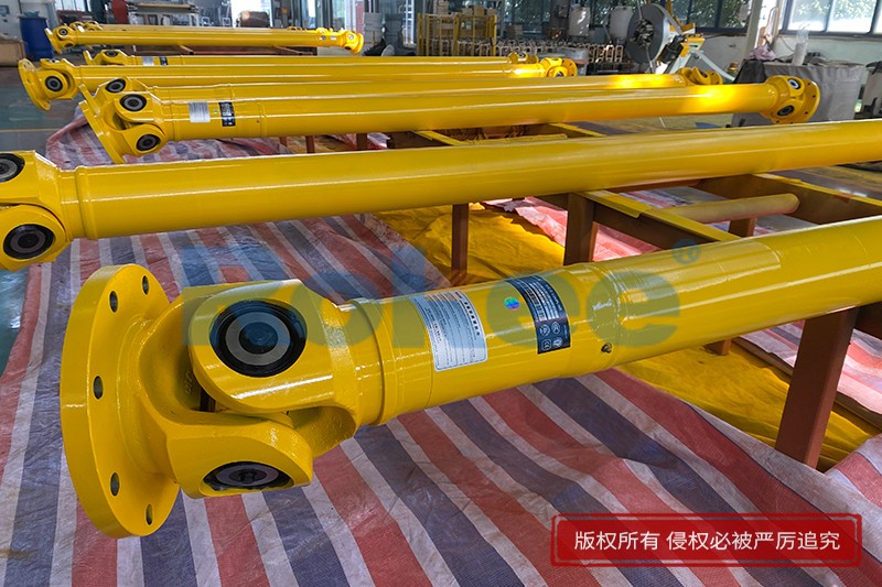
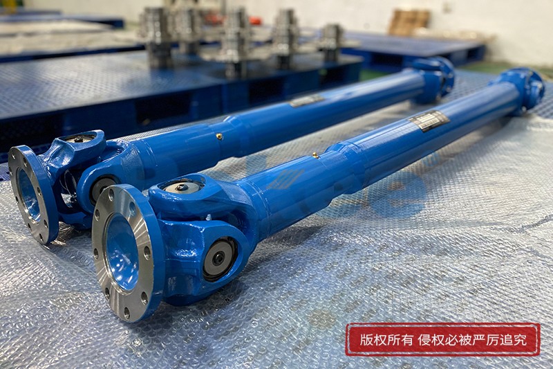
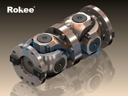
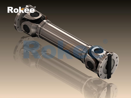
Apart from the above mainstream classification methods, cardan shafts can also be distinguished by connection modes at both ends, including flange-connected cardan shafts and yoke-connected cardan shafts. Flange-connected cardan shafts match circular flange plates with uniform bolt holes at two ends, achieving rigid surface contact and multi-point bolt fastening with connected power components. This connection mode provides excellent axial and radial positioning accuracy, strong anti-loosening performance and high overall structural rigidity, suitable for heavy-load and high-vibration working environments where connection stability is prioritized. Yoke-connected cardan shafts directly integrate joint yokes at shaft ends, realizing quick pin shaft connection with matching components. This design features simple assembly and disassembly processes and convenient daily maintenance, but the overall connection rigidity is lower than flange structures, with slight installation clearance easy to generate minor vibration during high-speed rotation. Yoke-connected types are mostly applied on light and medium-duty mobile machinery requiring frequent component disassembly and routine maintenance.
Each type of cardan shaft has inherent structural strengths and unavoidable limitations, so targeted type selection must combine four core operating parameters: maximum working deflection angle, rated transmission torque, rated working speed and operating environment. For low-speed, small-deflection and light-load auxiliary transmission scenarios, single-joint and light-duty fixed-length cardan shafts can meet demands with lower cost and simpler structure. For conventional vehicle chassis transmission and general medium-load industrial equipment, double cross-type telescopic cardan shafts remain the most cost-effective option with balanced performance across all indicators. For high-speed passenger transport equipment requiring ultra-smooth power output, ball-type constant-velocity cardan shafts are preferred to eliminate transmission vibration completely. For mining and construction machinery working under persistent heavy impact loads, ultra-heavy-duty flange-connected cross-type cardan shafts are irreplaceable due to outstanding structural durability. Improper type matching will directly trigger a series of operational faults: applying light-duty shafts for heavy loads leads to cross spider fracture and shaft body torsion failure; adopting cross-type shafts for long-term high-speed operation causes excessive noise and bearing overheating; using fixed-length shafts for movable mechanical transmission results in spline extrusion damage and joint sealing failure.
With the continuous advancement of material manufacturing technology and mechanical simulation optimization, all types of cardan shafts are undergoing iterative upgrading to overcome traditional defects and expand application boundaries. In terms of material optimization, traditional medium-carbon steel shaft bodies are gradually replaced by high-strength alloy steel and lightweight carbon fiber composite materials, reducing overall shaft weight while improving torsional fatigue resistance and corrosion resistance. In structural optimization, finite element dynamic simulation is adopted to adjust the thickness distribution of shaft tubes and stress concentration points of universal joints, lowering rotating vibration amplitude and extending service life without increasing structural weight. In manufacturing technology, precision cold forging and numerical control finishing improve component matching accuracy, reducing assembly clearance and minimizing abnormal friction inside joints. Meanwhile, integrated damping structures are added into partial cardan shaft products to further weaken residual vibration generated during power transmission. In the future, intelligent monitoring modules will be embedded into cardan shaft assemblies to collect real-time operating vibration, temperature and torque data, realizing early fault warning and predictive maintenance for vulnerable joint parts.
In conclusion, cardan shafts form a complete hierarchical product system through differences in joint quantity, internal joint structure, load grade, axial adaptive capability and end connection modes. No single type of cardan shaft can adapt to all mechanical transmission scenarios, and the rational selection depends on full consideration of actual working conditions and transmission performance requirements. From simple single-joint light-duty structures to complex reinforced ultra-heavy-duty double universal joint assemblies, all cardan shaft types follow the core design purpose of realizing stable torque transmission between misaligned shafts while making targeted trade-offs among structural complexity, manufacturing cost, rotating smoothness, deflection adaptability and impact resistance. As one of the most enduring and indispensable flexible transmission components in mechanical engineering, diversified cardan shaft types will continue to support the stable operation of mobile machinery, industrial production lines and special mechanical equipment. Mastering the characteristics and applicable scenarios of each cardan shaft type lays a solid foundation for mechanical transmission system design, equipment matching optimization and efficient whole-life cycle maintenance.
- Tags:
- Cardan Shaft Couplings ,
- Industrial Cardan Shafts ,
- Cardan Shafts ,
- Cross Cardan Shafts ,
- sandwich panel line ,
- sandwich panel machine
- pu sandwich panel machine
« Cardan Shaft Types » Latest Update Date: Jun 12, 2026
https://www.rokeecoupling.net/blog/cardan-shaft-types.html