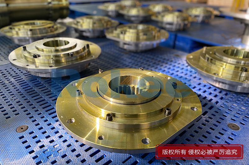
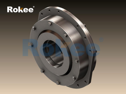
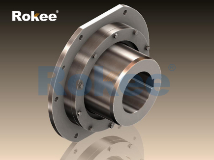
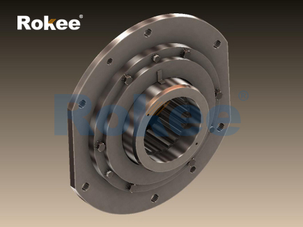
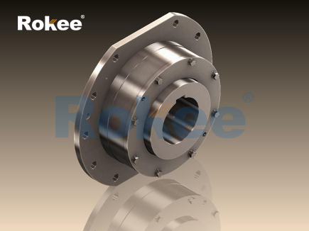
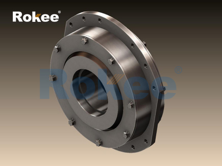
The barrel coupling stands as a flexible mechanical connection device designed to transmit torque between two rotating shafts while accommodating several forms of misalignment that commonly emerge during equipment operation. At its core, the working principle relies on the engagement between cylindrical barrel-shaped rolling elements and the matching curved grooves machined on the inner surfaces of two separate coupling hubs. When power transfers from the driving shaft to the driven shaft, rotational force passes through the hub, then pushes the barrel elements to roll along the contour of the grooves rather than sliding against contact surfaces. This rolling contact feature creates low friction between contact parts, reducing heat generation and wear even under continuous rotation. Minor deviations in shaft position, including radial offset, angular tilt and limited axial movement, can be absorbed by the slight displacement of barrels inside the grooves. Unlike rigid couplings that force shafts to maintain perfect alignment, this structure avoids imposing extra bending stress on connected shafts and bearings. The barrels maintain continuous contact with both hubs throughout the full rotation cycle, ensuring steady torque transmission without sudden interruptions. Proper contact distribution spreads load evenly across multiple barrel units, preventing localized stress concentration that could lead to premature component damage. Even with small misalignment present, the rolling motion preserves smooth rotation and minimizes vibration transfer across the joint, making this type of coupling suitable for power transmission systems where alignment cannot stay absolutely perfect all the time.

The geometric design of barrels and groove profiles directly shapes how the coupling responds to misalignment and torque loads. Each barrel element possesses a smooth cylindrical outer surface, and the grooves cut into each hub follow a curved path that matches the barrel radius. This matched curvature allows barrels to shift slightly within their seats when shafts move out of perfect alignment. When angular misalignment occurs between the driving and driven shaft, barrels tilt gently within the grooves instead of jamming. Radial displacement causes barrels to roll sideways within the available clearance space, while axial movement of either shaft permits barrels to slide along the length direction of grooves within a predefined range. The dimensions of barrels and groove depth determine the maximum allowable misalignment values, as excessive offset will force edge contact between barrels and groove edges, shifting the load from uniform rolling contact to concentrated point pressure. The number of barrel elements arranged around the circumference influences load sharing; more barrels distribute torque across a larger total contact area. Each barrel carries a portion of the transmitted torque simultaneously, so individual elements experience lower peak contact pressure. Careful surface finishing of barrels and groove surfaces reduces surface roughness, which further lowers friction and wear during long-term cyclic rotation. This coordinated geometry ensures that the coupling can flex under misalignment while retaining reliable torque transfer capacity under normal operating conditions.
Torque transmission dynamics in barrel couplings differ significantly from couplings that depend on elastomer materials to absorb movement. As the driving hub rotates, the side wall of each groove presses against the barrel surface, and the barrel then transfers this contact force to the groove wall of the driven hub. This force transfer occurs purely through mechanical contact between metal components, without any elastic deformation of soft intermediate materials. During steady rotation, the contact point between each barrel and groove moves continuously as rotation proceeds, creating a repeating cycle of load application. When torque increases, contact pressure on barrel surfaces rises proportionally, but the rolling nature of contact prevents high frictional losses seen in sliding contact joints. Under fluctuating torque conditions, such as load shocks from starting or sudden load changes, barrel elements can temporarily shift within grooves to buffer sharp impact forces. The rigid nature of barrel and hub materials means torsional stiffness remains relatively high compared to elastomeric couplings, so rotational phase difference between driving and driven shafts stays minimal. This characteristic makes barrel couplings effective for systems requiring precise rotational synchronization, even as they still accept shaft misalignment. However, heavy shock loads beyond the designed capacity can create permanent indentations on groove surfaces, disrupting the smooth rolling motion and introducing vibration in subsequent operation cycles.
The way barrel couplings handle different types of shaft misalignment requires clear separation of each motion type to understand operational limits. Angular misalignment develops when the centerlines of two shafts intersect at a small angle instead of lying along a single straight line. In this situation, barrels roll along the curved grooves and adjust their angle relative to the hub face, maintaining continuous contact across the full rotational circle. Radial misalignment arises when shaft centerlines run parallel but offset from one another. The barrels shift radially inside the groove clearance to follow this offset, and rolling movement continues without binding. Axial misalignment refers to linear movement of one shaft along its rotational axis, which barrels accommodate by moving along the longitudinal direction of the grooves. Each form of misalignment consumes part of the coupling’s total allowable movement capacity. When multiple misalignment types appear together, their combined effect must stay within the overall working range of the coupling. If misalignment exceeds the designed limits, barrels will ride up onto groove edges, creating high edge loading, abnormal noise, accelerated wear and potential damage to shaft bearings. Operators must recognize that the coupling absorbs misalignment through controlled movement of barrels, rather than eliminating misalignment entirely. The coupling protects connected machinery by preventing misalignment forces from transferring directly into bearings and other precision parts of the rotating equipment assembly.
Friction and wear behavior represent critical considerations for the long-term performance of barrel couplings. Rolling contact between barrels and groove surfaces produces far less friction than sliding contact, which keeps operational energy losses low. Still, microscopic sliding cannot be fully eliminated when barrels adjust position to compensate for misalignment. Small relative slip occurs at contact points whenever barrels tilt or shift radially and axially during rotation. This minor slip gradually causes surface material removal over countless rotation cycles. Surface hardness of barrels and hub grooves strongly affects wear rates. Hardened contact surfaces resist scratching and indentation, extending service life under continuous operation. Lubrication plays an essential role in reducing metal-to-metal contact. A thin layer of lubricant separates barrel and groove surfaces, lowering friction, carrying away heat generated at contact points, and blocking contaminants from reaching contact zones. Without adequate lubrication, dry metal contact leads to rapid abrasive wear, surface scoring and the formation of metal debris inside the coupling enclosure. Debris further accelerates wear by acting as abrasive particles trapped between rolling surfaces. Regular lubricant maintenance preserves the low-friction rolling mechanism and maintains stable torque transmission properties throughout the service life of the coupling assembly.
Vibration and damping characteristics of barrel couplings stem directly from their all-metal rolling contact construction. Compared with flexible couplings using rubber or polymer inserts, barrel couplings provide only limited damping ability. Most vibration originating from the driving side transfers through the barrel elements to the driven side with little attenuation. The coupling’s main advantage is not vibration absorption, but vibration reduction caused by removing extra bearing loads induced by shaft misalignment. When shafts are misaligned, rigid couplings generate large periodic forces that excite vibration in bearings and supporting structures. By permitting controlled relative movement between hubs, barrel couplings eliminate those reaction forces. Minor vibration still arises from small variations in contact load across barrels during rotation, especially when misalignment approaches maximum allowable values. Excessive misalignment creates periodic impacts between barrels and groove walls, producing noticeable noise and amplified vibration. Proper alignment within the coupling’s working range minimizes this periodic impact. While barrel couplings cannot dampen torsional vibration as effectively as elastomer alternatives, their high torsional stiffness preserves angular accuracy. This balance of properties makes them suitable for high-speed and high-torque applications where maintaining precise rotational timing is more important than suppressing torsional oscillation.
Installation and operational adjustment influence how well a barrel coupling functions according to its working principle. During assembly, the two hubs mount separately onto the driving and driven shafts, and barrel elements fit into the grooves between the hubs. Initial shaft alignment should be set as close to perfect as possible. The coupling is designed to compensate for residual small misalignment, but it is not intended to correct large installation errors. After assembly, visual checks and measurement can verify the clearance and positioning of barrels inside grooves. Once rotation starts, any residual misalignment triggers the barrels to roll and shift automatically to adapt to shaft position. Thermal expansion of connected equipment during operation often causes slow changes in shaft position. The barrel coupling accommodates these gradual dimensional changes automatically through barrel movement, preventing thermal stress buildup on shafts and bearings. Operators should monitor for warning signs of poor conditions, including unusual knocking sounds, rising operating temperature, or increased vibration levels. These signs usually indicate excessive misalignment, degraded lubrication, or surface damage on barrels and grooves. Continuous monitoring allows timely maintenance before small defects escalate into catastrophic failure of the power transmission system.
Limitations and application boundaries define where barrel couplings perform well and where alternative coupling designs become more appropriate. The rolling contact mechanism works reliably for steady and moderately fluctuating torque loads, but repeated heavy impact loads may damage contact surfaces over time. All-metal construction means barrel couplings lack electrical isolation between connected shafts, so electrical current can pass through the coupling assembly. This feature makes them unsuitable for applications requiring insulation between driving and driven equipment. Their relatively low damping capacity also restricts use in systems with strong torsional vibration. Meanwhile, the coupling excels in high torque and high-speed operating environments, and in machinery that requires accurate angular synchronization. It handles combined radial, angular and axial misalignment in a compact structural form, without relying on easily degradable polymer components. Understanding the fundamental working principle helps equipment designers and maintenance personnel judge whether this coupling matches the load, speed, alignment and environmental requirements of a given power transmission setup. Correct application of barrel couplings delivers stable torque transfer, protects supporting bearings, and extends the overall service life of rotating machinery systems.
- Tags:
- Barrel Couplings ,
- sandwich panel line ,
- sandwich panel machine
- pu sandwich panel machine
« Working Principle of Barrel Couplings » Latest Update Date: Oct 20, 2026
https://www.rokeecoupling.net/blog/working-principle-of-barrel-couplings.html